
1C:Enterprise 8.3. Developer Guide. Contents
CONFIGURATION OBJECTS
This chapter contains instructions for working with the entire configuration and describes modes and mechanisms that are used for all configuration objects.
Creation and setup of the main configuration objects (constants, catalogs, documents, sequences, logs, enumerations, reports, data processors and registers) and some other objects located in the Common configuration branch (filter criteria and styles) are described in the documentation using an example of the object editing window (see page 59 for more details). The same can be done using the object properties palette.
5.1. CONFIGURATION PROPERTIES
Configuration as a whole has its own editable properties. The properties palette opens for the root of the configuration tree.
In addition to the general properties available for each configuration object (see page 250), the configuration also has features described below.
5.1.1. General Property Category
Default run mode – selects a default run mode for the system (Managed application or Ordinary application). A new configuration always has this property set to Managed application. The run mode can be modified for a system user (see "1C:Enterprise 8.3. Administrator Guide"). This property cannot be changed if the Compatibility mode property is set to Version 8.1.
Use purposes – specifies the purpose for which an application is used (Mobile device or Personal computer). The property is only available if the Default run mode property is set to Managed application. The available configuration functions change depending on the selected purpose.
Mobile device – supports development of an application for use on a mobile device (for further details, see page 2-917). A limited number of application objects is available to the developer (for a list of limitations, see page 2-1247);
Personal computer – supports development of an application that cannot be used on a mobile device and functions as a managed application;
Both options are selected (Mobile device and Personal computer) – supports development of an application that would contain objects available both on a mobile device and within a managed application on a desktop computer. Please note the following:
If Personal computer is not mentioned in the purpose of use:
○ The default run mode cannot be changed.
○ Properties that are not used on a mobile platform are unavailable in the properties palette (see page 1-53).
○ Only those types of objects available on a mobile platform can be used as types of attributes.
If configuration purposes contain the option Mobile application:
○ The module check uses settings for the Mobile application mode. By default, this mode is prompted to change when the settings are edited.
○ The configuration check uses a separately stored setting for the executed procedures.
○ The Syntax assistant uses a separately stored setting for the applied filters.
Script variant – selects the default programming language (Russian or English). The selection defines which language is used to generate language constructs in modules (for example, when using the Syntax Assistant) and display information about primitive data types. Either the Russian or the English version of language constructs can be used regardless of the value of this property. When you change the value, the language of already entered language constructs does not change.
Default Role – selects the default role of the configuration. The role specified here will be used if the configuration user list is empty and access authorization is not performed when the program is launched. In this case it is assumed that user has administrative permissions regardless of the actual Administration right setting in the role specified as the default role. If the configuration default role is not specified and the user list is empty, the user will work without access right restrictions. Roles are specified in the Common – Roles branch of the configuration tree (see page 1-180).
The default run mode should match the default role as far as rights to the applications launched are concerned. For instance, if Default run mode is set to Managed application, and the right Thin client is disabled for the main role, the user will not be able to work with application with a thin client.
Managed application module – click the Open link to open the editing window for the managed application module (see page 1-171).
Session Module – click the Open link to open the session module editing window (see page 1-172).
External Connection Module – click the Open link to open the application module editing window (see page 1-172).
Use managed forms in ordinary application – specifies that managed forms need to be used in the ordinary application mode of the thick client. Selecting this check box changes rules of form selection in the thick client (for details see page 1-263) and rules of centralized configuration check (for details see page 2-1025).
NOTE
This property is only available if the configuration editing mode is set to Managed application and ordinary application.
Use ordinary forms in managed application – specifies that ordinary forms need to be used in the managed application mode of the thick client. Selecting this check box changes rules of form selection in the thick client (for details see page 1-263) and rules of centralized configuration check (for details see page 2-1025).
NOTE
This property is only available if the configuration editing mode is set to Managed application and ordinary application.
Additional full-text search dictionaries – selects common templates or constants to be used as additional full-text search dictionaries (see page 2-839).
Common settings storage – storage is used to store various application settings. The platform does not write any settings to the storage independently. The developer should use the storage indicated in this property in the 1C:Enterprise script to save or restore user application settings.
Report settings storage – storage contains user report settings.
Report variants settings storage – storage contains report variants.
Form data settings storage – storage contains form data. You can use this storage to save data processor attributes, for example. Please note that you can select a different storage for each report or data processor.
Dynamic list user settings storage – this is the storage to store dynamic list settings.
For more details on storages and how they work see page 1-223.
5.1.2. Presentation Property Category
Command interface – click Open to open an editor to specify viewability of default subsystems on the start page (also from the perspective role).
Start page working area – click Open to open a setup form to specify which forms are placed on the start page and what template will be used to create a work area.
Main section command interface – click Open to open a command interface setup dialog for the main section.
Main section picture – this property can be used to change the picture of the main section on the sections panel.
Client application interface – is used to setup the default panel layout for the Taxi interface. The interface will change to this if a user clicks Default in the panel editor (see page 1-108).
Default Language – specify default language for the configuration.
Brief Information – brief information on the configuration.
Detailed Information – detailed information on the configuration (multiple lines allowed).
Logo – select a logo. Make your selection in the standard picture selection window:
Fig. 61. Picture Selection
NOTE
A logo must be 64x64 pixels or smaller. Picture type may be any of those supported by the 1C:Enterprise system.
Splash – use this option to select a splash. A splash is selected in the standard picture selection window. The picture to be used as a splash must be 600x255 pixels. Transparency is not supported.
NOTE
The splash screen picture must meet the following requirements: 305x110 pixels in size; you can set transparent color when selecting the picture. Picture type may be any of those supported by the 1C:Enterprise system.
Copyright – information on the configuration author.
Vendor information address – link to the information about the configuration vendor (specified in the Copyright property). The address can be set with a schema prefix (http://) or without it.
Configuration information address – link to information about the configuration. The address can be set with a schema prefix (http://) or without it. The About 1C:Enterprise window displays the following data: configuration Synonym, Configuration information address property, Copyright property and Vendor information address property.
Default Constants Form – select the default form for input and editing of constants in the configuration. This form is selected from among the common forms (see page 1-229) in Common – Common forms. For details on the various forms, see page 1-263.
NOTE
This property is only available if the configuration editing mode is set to Managed application and ordinary application.
The Default report form, Default report settings form and Default report variant form properties can be used to specify the default forms that will be used by reports without the corresponding form being specified. For example, you can create a default report form containing some features that should be present in all application forms, such as sending the report generated by e-mail. To solve such a task, you need to create a default report form, implement all the necessary commands and specify it in the Default report form configuration property. After this action all reports for which a default report form is not specified will use the default form you created.
Default dynamic list settings form specifies a general form to be used to edit the dynamic list settings in the application. If this property is not set, an automatically generated settings form will be used to edit the dynamic list settings.
The property Default search form specifies a general form to be used instead of a system form for a full text search, which can be called in the Taxi interface from the toolbar or through a keyboard shortcut.
5.1.3. Development Property Category
Properties in this category describe data on configuration vendor and version (for details see page 2-1122).
Update directory address – contains address of a resource that can be used to update the application solution.
5.1.4. Help Content Property Category
Include in Help Content – if this property is set, help content is included in the general description of the configuration.
Help content – click Open to open the configuration description editing window.
5.1.5. Compatibility Property Category
Data lock control mode – option of controlling data locks in a transaction (see page 1-509).
Objects Autonumbering Mode – defines whether automatically assigned object numbers can be re-used if they are not stored in the database.
This property can be set to Release Automatically to ensure numbering works in the same way as in 1C:Enterprise 8.0. Automatically assigned numbers and codes are re-used later if the object they are assigned to is not recorded.
You can set Do not Release Automatically for this property if you want objects requiring continuous numbering to be assigned numbers upon recording rather than opening a form.
Modality usage mode – specifies whether methods to open modal windows can be used in the application. If the property is set to Use, modal windows can be used with no limitations. If the property is set to Do not use, modal windows cannot be used in this application. If an attempt is made to use such modes, an error will be diagnosed (also during the script text syntax control). Use blocking windows instead of the modal ones (see page 1-426). If the property is set to Use with warnings, no error will be diagnosed during the attempt to use modal windows, but a message box will display a message that use of modal windows is prohibited in this mode. Use of blocking windows instead of modal ones is likewise recommended in this mode.
Interface compatibility mode – the property controls the client application interface mode.
Version 8.2 – the client application uses interface version 8.2. Switching to the Taxi interface is not supported.
Version 8.2. Taxi allowed – interface version 8.2 is used by default. The user can switch to the Taxi interface via the parameters dialog, the ClientSettings object, or the command bar.
Taxi. Version 8.2 allowed – Taxi interface is used by default. The user can switch to interface version 8.2 via the parameters dialog, the ClientSettings object, or the command bar.
Taxi – the client application works in the Taxi interface. Switching to interface version 8.2 is not supported.
If interface version 8.2 is used, the system supports switching between the interface in separate windows and between this interface in tabs.
If Compatibility mode is set to a value that exceeds Version 8.3.2 (None, Version 8.3.3, or a later version), and property Interface compatibility mode is set to Version 8.2 or Version 8.2. Taxi allowed, a tabbed interface will automatically be set for any new users of the application.
Picture PictureLib.Help displays differently if the Interface compatibility mode property is set to Taxi or Taxi. Version 8.2 allowed and in other cases.
Compatibility mode – this property controls the behavior of mechanisms that have been changed in a new version if compared with theprevious one. This property can have the following values: Version 8.3.2, Version 8.3.1, Version 8.2.16, Version 8.2.13, Version 8.1 and None. See page 2-1214 for details of the system’s work with any version in compatibility mode.
Configuration operations with an unknown compatibility mode are not supported. Unknown compatibility modes are modes which are compatible with the functionality implemented in later 1C:Enterprise versions. For example, if the None compatibility mode is set in version 8.3.1, it will be regarded as unknown when the configuration is open in version 8.2.16. And if the Version 8.2.16 compatibility mode is set in version 8.3.1, then it will be displayed as None in version 8.2.16. If no new compatibility mode is set in any particular version, the behavior of the None mode will be the same as in the previous version. When you attempt to run or restore the configuration with an unknown compatibility mode, an error message will be returned indicating the version required. Restoration of 1cv8. dt files generated in version 8.3.1 and later is not permitted in later versions of 1C:Enterprise (older than 8.3.1), except where the Compatibility mode configuration property is set to Version 8.2.16 in version 8.3.1.
When configurations of 1C:Enterprise 8.1 (or older versions) are converted, the property will have the Version 8.1 value. Generally speaking, when you open a configuration of any later versions of 1C:Enterprise, the Compatibility mode property will be set to a value compatible with the previous version if such a mode is selected in the new version.
If you want to ensure that the application solution operates in multiple versions of 1C:Enterprise simultaneously (including versions for which a compatibility mode is available), it is recommended first to obtain the current platform version in different locations from where the code will be called, and then compare it with the compatibility mode (if necessary).
If the infobase was opened using version 8.2.14 you can transit to version 8.2.13 only if the configuration did not use new features of version 8.2.14. For a file mode variant, migration from version 8.2.14 to version 8.2.13 is performed with infobase download/upload.
5.2. MANAGED APPLICATION MODULE
A managed application module launches automatically when a configuration is loaded during 1C:Enterprise startup in the following modes.
thin client
web client
thick client in the managed application mode
The managed application module is used for processing tasks related to the user session (primarily for processing session start and end events). The managed application module is inaccessible to procedures working on the server. We recommend using it to implement event handlers only.
Procedures and functions of the managed application module, along with its variables that have the Export keyword in their titles, can be accessed in:
non-global common client modules
client methods of form modules
client methods of command modules
In managed application module context you can use exported procedures and functions of common modules.
The managed application module is a component of the configuration and is stored only in the configuration. The File – Save command launches the procedure of saving changes for the entire configuration.
5.3. EXTERNAL CONNECTION MODULE
External connection module may contain exported variables, procedures and functions as well as handler procedures for OnStart() and OnExit() events used in external connection mode (see section "Integration and Administration Tools" in the 1C:Enterprise script help).
5.4. SESSION MODULE
Session module runs automatically when the configuration is loaded during 1C:Enterprise system startup.
The session module is used to initialize session parameters and process sessionrelated actions. The session module is always performed in privileged mode in the 1C:Enterprise server cluster.
IMPORTANT!
Session modules can only contain definitions of functions and procedures.
It cannot contain exported procedures or functions. It can use procedures from the configuration common modules.
Session parameters are set in the SessionParametersSetting() event handler.
The session module is executed after the application module (external connection module) is launched, but before calling the BeforeStart event handler (OnStart, for the external connection module).
5.5. COMMON CONFIGURATION BRANCH
This section describes configuration objects, such as Subsystems, Common modules, Session parameters, Roles, Common attributes, Exchange plans, Filter, Event subscription, Scheduled jobs, Functional options, Functional options parameters, Defined types, Settings storages, Common forms, Common commands, Command groups, Interfaces, Common templates, Common pictures, XDTO packages, Web-services, WS-references, Style items, Styles and Languages. These objects do not describe data structure and data processing mechanisms. They are used to set rules for working with data, to describe supplementary objects used
for making different forms in the data exchange mechanism and they also contain common modules and templates of print forms accessible from any configuration module.
5.5.1. Subsystems
For a description of subsystem purposes see page 1-343.
NOTE
Setting Desktop as a subsystem name is not recommended.
The number and nesting levels of objects at the Subsystems branch are unlimited.
To view configuration objects for a specified set of subsystems, you can set an object filter in the Configuration window. Select Actions – By Subsystems in the Configuration window and specify a required set of subsystems, then set additional filter criteria, Include objects from subordinate subsystems and Include objects from parent subsystems.
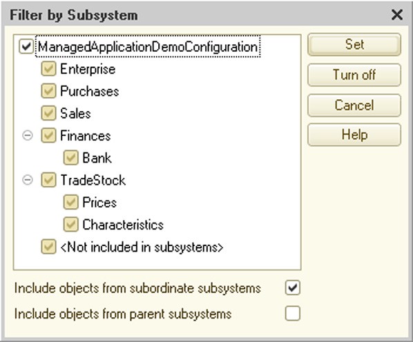
Fig. 62. Filter by Subsystem
The subsystem list contains a special item, <Not included in subsystems>, which you can use to select only those objects that do not belong to any subsystem.
NOTE
When filtering by subsystems is set, key configuration object tree branches without filtered objects are not shown.
The user interface defines whether configuration objects belong to a particular subsystem.
The Subsystems configuration object property value can be accessed in the program using the 1C:Enterprise script tools. This provides additional options for data filtering.
The Move subsystem command in the context menu can be used to change subsystem subordination in subsystem hierarchy.
Use the Content tab in the subsystem editor to bind metadata objects to a particular subsystem.

Fig. 63. Set of Subsystems
The upper part of the window displays all configuration objects that can be assigned to individual subsystems. Placing a checkmark next to an object (e.g., Contractors on fig. 63) means that this object is included into the subsystem and is displayed in the lower part of the window. You can see all objects belonging to the subsystem being edited at the bottom of the window.
If the Include in Help Contents property is set, the help contents will include the branch showing help for the subsystem and all objects included in the subsystem. If the property is reset, the help contents will not contain such a branch (describing the subsystem and included objects), but help for the objects included in the subsystem will be available directly in object forms.
5.5.2. Common Modules
Objects in the Common modules configuration branch are used for storing texts of functions and procedures that may be called from any other configuration module.
IMPORTANT!
A common module can contain definitions of functions and procedures only.
Procedures and functions of the common module that have the Export keyword in their titles belong to the global context. Detailed information on writing procedures in a common module can be found in sections "Source Text Format in Program Modules" and "Operators" of the 1C:Enterprise script help.
To edit a common module, click Open in the Module property at the properties palette of Common Modules object type in the Configuration window. Text of the common module is opened in the 1C:Enterprise text editor in module text editing mode.
A common module is a component of the configuration and is stored in the configuration only.
The Global property defines if the common module exported methods belong to the global context.
If the Global property is set to True, the common module exported methods are available as methods of the global context.
If the Global property is set to False, a property is created in the global context and its name matches the common module name in the metadata. This property is read-only. Value of this property is the CommonModule object. Through this object, exported methods of this common module are exposed. Therefore, syntax for calling a non-global common module method looks like XXXXX.YYYYY where XXXXX is the property name in the common module context and YYYYY is the name of the common module exported method.
Example:
TradeEquipmentOperation.PlugInBarcodeReader();
5.5.2.1. Various Contexts and Common Modules
Using properties of common modules and preprocessor instructions, you can arrange execution of various common module methods in the right context.
Each property of a common module is responsible for compilation (and execution) of this common module in a particular context.
You can use the following properties that are responsible for the context where common module methods are available:
Client (ordinary application) – common module methods are only available for the thick client in the ordinary application mode;
Client (managed application) – common module methods are available for the thin client, web client and thick client in the managed application mode;
Server – common module methods are available at the server;
External connection – common module methods are available in an external connection.
If multiple properties are set simultaneously, it means common module methods are available in multiple contexts.
If a common module has its Server property set along with another property, it means this module is available at the server and the selected client. You should keep in mind that you would have multiple variants of compiled code (for the selected clients and the server).
If a method located in this common module is called by the client, it uses the client copy of the module; if called by the server, it uses the server copy. In this case you can use preprocessor directives (for details see page 1-159) to "protect" the server from the code it cannot execute.
Consider the following example. A common module that can run at both the thin client and the server owns a method which behaves differently depending on where it is executed: the thin client or the server. Consider how you can handle this:
Procedure  CommonModuleMethod() Export

// Enter important code here
#If  ThinClient Then

// Display warning
ShowUserNotification("At client");
#EndIf

EndProcedure
The server-side code looks like the following:
Procedure  CommonModuleMethod() Export

// Enter important code here
EndProcedure
The code on the thin client side looks like the following:
Procedure  CommonModuleMethod() Export
// Enter important code here

// Display warning
ShowUserNotification("At client");

EndProcedure
You can use different methods to transfer control from the client to the server:
call methods of the server-side common module;
in the form or command module, call a method preceded by compiler directives &AtServer, &AtServerNoContext (for details on form modules see page 1-390).
Please note that server procedures do not support calls to methods of client common module (without their Server property set) or to client methods of form and command modules. Control is transferred back to the client after the most external call to a server method is complete.
This does not apply to form and command module methods preceded by compiler directives &AtClientAtServer, &AtClientAtServerNoContext (for details see page 1-390).
Please keep in mind the following points:
While writing code for a common module that is available to multiple clients, you should consider maximum limits which might be imposed by clients or use preprocessor instructions to "isolate" client-specific code.
Preprocessor instructions are also useful if a common module has multiple execution contexts, e.g., an external connection and a thin client or a client and a server (as is often the case). In this case preprocessor instructions enclose interactive code that cannot run at the server and can be executed at the client (see the example above).
For details on preprocessor instructions and compiler directives see page "Use preprocessor instructions and compiler directives to allow use of procedures and functions from various modules (for information about module types see page 1-115)." on page 1-177 and section "Execution of Procedures and Functions" in the 1C:Enterprise script help.
To control calls to exported methods of the server-side common module in the client code, use the Server call property. If this property is set, exported methods of the server-side common module can be called by the client. If this property is not set, you can only call exported methods from server-side methods (both methods of server-side common modules and server methods of form and command modules).
TIP
It is recommended to set the Server call property to False if the server-side common module contains methods that are not recommended to be called by the client (e.g., for safety reasons).
NOTE
If the Client (ordinary application), Client (managed application), External connection properties are set simultaneously, the Server call property is cleared automatically. If the Server call property is set, the Client (ordinary application), Client (managed application) and External connection properties are automatically cleared, provided that they were set simultaneously.
The Privileged property can be used to disable control over access rights when executing common module methods.
IMPORTANT!
If the Privileged property is set for the common module, its Server property is set automatically and other properties are cleared (Client (ordinary application), Client
(managed application) and External connection). The privileged common module can only be executed at the server.
For details on the privileged mode see page 1-181.
5.5.2.2. Reuse of Return Values
If a common module is not global, its Reuse return values property becomes available. This property can have the following values:
Do not use – return values for common module functions are not reused;
During call and During session – method of data reuse definition is used for the common module. The essence of this method is that the system stores function parameters and execution results after the first call. Next time the function is called with the same parameters, the stored value (from the first call) is returned without the function being executed. If parameter values are changed during execution, this method is not used upon the next call of the function.
Storing call results is characterized by the following:
if a function is executed on the server and is called from the server code, parameter values and call results are stored for the current session on the server side;
if a function is executed on a thick or thin client, parameter values and call results are stored on the client side;
if a function is executed on the server, but is called from the client code, parameter values and call results are stored both on the server side and on the client side.
Stored values are deleted:
If the property is set to During call:
○ on the server side – when control is returned from the server;
○ on the client side – upon completing execution of a procedure or function of the 1C:Enterprise script (called by the system from the interface rather than another procedure or function of the 1C:Enterprise script).
If the common module property is set to During session:
○ on the server side – when the session is finished;
○ on the client side – when the client application is closed.
Stored values can be deleted:
at the server, thick client, external connection, thin client and web client with regular connection speed – 20 min. after the stored value is evaluated or 6 min. after its last use;
at the thin client and web client with low connection speed – 20 min. after the stored value is evaluated;
if there is not enough RAM in a server working process;
if a working process is restarted;
if a client is switched to another working process.
If values are deleted, an export function is called identically to the first call.
This common module property does not affect procedure execution: procedures are always executed.
If return values reuse is set for a common module, the list of export function parameter types becomes limited. Parameters can only be of the following types:
Primitive types (Undefined, NULL, Boolean, Number, String, Date);
Any references to database objects;
Structures with property values of the above types. In this case parameter identity is controlled based on structure content.
If the Reuse return values property is set to During session in the common module, values returned by functions of this module can't use TempTablesManager type values.
Where the function of a common module with the reuse option selected is called from the same common module (e.g. named CommonModule), it should be remembered that if the function is called by the MyFunction() name, the function will be executed every time the function is called. To make use of saved values, the function should be called by its full name: CommonModule.MyFunction().
RefreshValuesReuse() global context method removes all reused values both at the server side and at the client side, regardless of the method call location. After the RefreshValuesReuse() method is executed, the first function call is executed afresh.
5.5.3. Session Parameters
Session parameters are mainly used in queries and conditions of data access restriction for the current session.
Using session parameters reduces data access time by excluding linked tables.
You can set session parameters using the properties palette.
Each session parameter may have two access rights: Get and Set (see below for details on access rights). If the Set right is removed, session parameter may be initialized only in a common module with the Privileged property set or in a session module.
Session parameters are initialized in the SessionParametersSetting() event handler of the session module (see page 1-172).
Prior to initialization, the session parameter is in Not Set state. An attempt to read this parameter calls the SessionParametersSetting() event handler first. If after the call the parameter is still Not Set, it raises an exception.
You should be able to discriminate between applications of session parameters and global variables of a managed application module (external connection module). The main differences of session parameters include:
Session parameters are metadata objects, meaning that 1C:Enterprise can exercise a tighter control over their use.
Session parameters are typed. A list of session parameter types is limited. Their common feature is inability to modify the inner state for objects of these types.
To set or get a value for a session parameter, the current user should have sufficient rights.
In the client/server mode, session parameter values are stored at the 1C:Enterprise server and are available from both the server and the client.
Session parameters are available both in the 1C:Enterprise script, for example:
SessionParameters.CurrentUser = UserName()
and access restrictions, for example:
Document.Report.User = &CurrentUser
In the latter case getting a session parameter value does not require the current user to have corresponding rights.
NOTE
If one of the following types is set for the session parameter: FixedArray, FixedCollection or FixedStructure, the Undefined value can be used as a collection element value.
5.5.4. Roles and Access Rights
5.5.4.1. Overview
Each user of the system should have free access to common information, e.g., common catalogs, constants or enumerations.
On the other hand, each user must have access only to the information they need in their work, and their careless actions must not affect work of other users or operability of the system as a whole.
The 1C:Enterprise Designer provides developers with advanced administration tools that can resolve this issue.
The required number of typical roles is created together with configuration. Roles describe rights of various user categories to access information handled by the system. You can assign a wide range of roles – from ability only to view a limited number of document types to a full set of rights to enter, view, update and delete any type of data.
There are two types of access rights in 1C:Enterprise – basic rights and interactive rights. Basic rights are always checked regardless of how infobase objects are accessed. Interactive rights are checked whenever interactive activities are performed (viewing/editing forms etc.) For available access rights see page 2-1209 (or a description of the AccessRight() global context method in the Syntax Assistant).
If the View right is set (granted) for an object with data in a form, but the Edit right is not set, this attribute is displayed in the form (with the attribute value displayed in the control associated with this object), but the value is unavailable for editing. If the View right is removed (withdrawn), an attempt to open the form displays an "Access violation!" warning, and the form fails to open.
When editing roles, note the internal right hierarchy in the list of rights. The hierarchy is based on the precedence of the rights. When any right is removed, every lower-level right associated with it is also removed and, conversely, when a lower-level right is set, any higher-level rights removed are also set. So removing the View right causes the Edit right to be removed. This is quite reasonable since it does not make sense to grant an edit right when a control associated with the data cannot be shown. Generally, rights can be granted for:
the entire configuration
objects
object attributes
tabular sections
tabular section attributes
standard attributes
When a new role is created, the following access rights are set for the configuration root object: ThinClient, WebClient, UserDataStorage and Output.
5.5.4.2. Privileged Mode of Operation
Code fragments can run in ordinary or privileged mode at the 1C:Enterprise server. The privileged mode does not require an access check at the record level or a rights check and allows any operation, thus accelerating module execution.
You can manage the privileged mode, i.e. enable or disable it, using the SetPrivilegedMode() global context method.
IMPORTANT!
In the client/server mode calling this method has no impact if you work at the client side.
The privileged mode is disabled by default.
The privileged mode should be enabled as many times as it is disabled. However, if the privileged mode was enabled within a procedure or a function (once or multiple times) and was not later disabled, the system disables it automatically as many times as it was enabled in the procedure or function without being disabled.
If a procedure or function calls the SetPrivilegedMode(False) method more often than it calls the SetPrivilegedMode(True) method, an exception is raised.
The PrivilegedMode() function returns True if the mode is on and False if it is completely off. It does not count how many times the privileged mode has been enabled in a particular function.
You might need to set the privileged mode programmatically if you perform mass operations with infobase data and do not need to check data access rights. Assume a user is responsible for recalculation of product prices. In this case the data processor that performs this operation can check the right of the current user to run it, and then the privileged mode can be enabled to perform all the required actions in the database. The user might have no rights to view the prices. However, since this data processor only recalculates the prices without showing them to the user, the task of access restriction is also performed.
You can also start a privileged session. In this session, a privileged mode is set from the very start of work. During operation, mode PrivilegedMode() will always return True, and disabling the privileged mode is not supported. To start a privileged mode, the user shall be assigned administrative rights (Administration rights). To launch a session, use the UsePrivilegedMode key of the client application launch command line, or the prmod parameter of the line used to connect to an infobase.
5.5.4.3. Safe Mode of Operation
If you need to use unsafe code at the server, e.g., external data processors or code entered by the user in Execute() and Evaluate() methods, you can use the safe mode.
In the safe mode:
Privileged mode is disabled.
Transition to privileged mode is ignored.
Operations using tools that are external relative to the 1C:Enterprise platform are not allowed:
○ COM-mechanisms:
□ COMObject()
□ GetCOMObject()
□ HTMLDocumentShell.GetCOMObject() ○ Loading add-ins:
□ LoadAddIn()
□ AttachAddIn()
○ Access to the file system:
□ ValueToFile()
□ FileCopy()
□ MergeFiles()
□ MoveFile()
□ SplitFile()
□ CreateDirectory()
□ DeleteFiles()
□ New File
□ New xBase
□ HTMLWriter.OpenFile()
□ HTMLReader.OpenFile()
□ XMLReader.OpenFile()
□ XMLWriter.OpenFile()
□ FastInfosetReader.OpenFile()
□ FastInfosetWriter.OpenFile()
□ XMLCanonicalizingWriter.OpenFile()
□ XSLTransform.LoadFromFile()
□ ZipFileWriter.Open()
□ ZipFileReader.Open()
□ New TextReader()
□ New TextWriter()
□ New Picture(), if the first parameter is a string
□ Picture.Write()
□ New BinaryData()
□ BinaryData.Write()
□ FormattedDocument.Write()
□ GeographicalSchema.Read()
□ GeographicalSchema.Write() □ GeographicalSchema.Print()
□ SpreadsheetDocument.Read()
□ SpreadsheetDocument.Write() □ SpreadsheetDocument.Print()
□ GraphicalSchema.Read()
□ GraphicalSchema.Write() □ GraphicalSchema.Print()
□ TextDocument.Read() □ TextDocument.Write()
○ Internet access:
□ New InternetConnection
□ New InternetMail
□ New InternetProxy
□ New HTTPConnection
□ New FTPConnection
IMPORTANT!
When forbidden operations are performed at run time, an exception is raised.
NOTE
External reports and data processors opened using File – Open are executed in the safe mode if the user has no administrative access rights.
The safe mode should be enabled as many times as it is disabled. However, if the safe mode was enabled within a procedure or a function (once or multiple times) and was not later disabled, the system disables it automatically as many times as it was enabled in the procedure or function without being disabled.
If a procedure or function calls the SetSafeMode(False) method more often than it calls the SetSafeMode(True)method, an exception is raised.
The configuration developer might need to set the safe mode programmatically if he or she intends to use code that is external relative to the configuration and is not absolutely reliable. An example would be execution of Execute() and Evaluate() methods when executable code comes from outside the system. In this case setting the safe mode before executing these methods would be a good practice.
//  The code to be executed is generated
//  The code could be loaded from external sources
//  or entered manually
ExecutableCode  = GetExecutableCodeFromOutside();

//  Enable the safe mode
SetSafeMode(True);

//  Execute the potentially dangerous code
Execute(ExecutableCode);

//  Disable the safe mode
SetSafeMode(False);
5.5.4.4. Data Deletion Modes
The 1C:Enterprise system enables users to delete unnecessary or obsolete information in two modes:
direct deletion of objects when use of deleted objects in other database objects is not analyzed;
reference integrity control enabled when objects are first marked for deletion and then checked for being referenced by other objects.
If the user has the right to use direct deletion mode, additional responsibility is laid both on the user that deletes the objects and on the system administrator who determines user rights and system operation with unresolved references. For example, specialists debugging the configuration can use system operation without reference integrity control. If reference integrity control is not used, objects are deleted directly (without deletion marks) and unresolved references can appear.
The most radical method of setting the reference integrity control mode is fully disabling the right to directly delete entire objects. This method prevents any direct deletion of objects within a given configuration. Users are only able to mark objects for deletion.
Please note that you can directly delete objects using the 1C:Enterprise script tools. Therefore, items of a specific configuration can directly delete objects bypassing reference integrity control. In this case a specialist who configures the system is responsible for data integrity.
5.5.4.5. Rules of Role Sets
Roles are usually specified for each activity. When a new user is added to the user list (see "1C:Enterprise 8.3. Administrator Guide"), a certain role or a set of roles is assigned to this user. If the user has multiple roles, the access algorithm for each object and right (e.g., Interactive Mark for Deletion) works as follows: if any of the roles has permission, access is granted; if no roles have permission, access is denied.
5.5.4.6. Access Rights Editor
The left part of the rights editing window contains a configuration object tree for all subsystems. The right part of the same window displays a list of rights for the selected configuration object. If an action is checked, it is allowed.
Thus, a user with the Salesperson role can view a GoodsReceipt document, but cannot add it interactively (see fig. 64).
The Set rights for new objects check box defines whether a certain role has rights for newly added configuration objects (it is cleared by default for a new role).
The Set rights for attributes and tabular sections by default check box defines whether this role has rights for attributes (including standard attributes) and tabular sections (including standard tabular sections) of new configuration objects (it is selected by default).
When you change the status of the Set rights for attributes and tabular sections by default check box, the system prompts you to change (select or clear) access rights for all attributes (including standard attributes) and tabular sections (including standard tabular sections) of all configuration objects. If you reject this action, no change is made in the existing objects; however, default behavior of new objects is modified.

Fig. 64. Editor of Role Access Rights
When a new role is created, the Designer sets the following for all rights:
rights are not granted for objects.
rights are granted for attributes (including standard attributes) and tabular sections (including standard tabular sections).
The Independent rights of subordinate objects checkbox defines how the system considers the parent object rights when it determines the rights for a subordinate object. If the checkbox is checked, parent object rights are not considered. If the checkbox is reset, the corresponding parent object right is analyzed to determine any subordinate object rights. If the parent object does not have the right, the subordinate object will also not have the right, regardless of the subordinate object right state.
Even if Independent rights of subordinate objects is selected, the right to a subordinate object requires that the same right be held to the parent one. That means that an attribute or a tabular part requires the right to an object, while the tabular part attribute requires the right to a tabular part or an object. This property matters if a user is assigned several roles with rights added via "OR". That means that if a role has the Independent rights of subordinate objects property set, and there is only a right to an attribute, while another role has the right to an object only, the user will have the right to an attribute only when the rights of these roles are added.
When setting attribute (tabular sections) access rights for reports/processes, please note the following: if the Independent rights of subordinate objects checkbox is unchecked and the Edit right is set for the attribute (tabular section), and the View right is not set for the report/processes, it will be assumed that the Edit right is also not set for the attribute (tabular section).
If multiple roles are assigned to a user, the parent object rights are validated before rights per role are combined (see page 1-185).
The Independent rights of subordinate objects check box affects the following objects:
attributes (including standard attributes)
tabular sections (including standard tabular sections)
tabular section attributes (including standard tabular section attributes)
commands
To change an access right, select a configuration object in the left-hand list and select or cleat the check box for the required action in the right-hand list. If you need to modify access to all objects in a branch, select it in the left-hand window and make the required changes in the access rights.
A description of each role can be displayed in a spreadsheet or text document using Actions – Output list.
5.5.4.7. View and Edit All Roles
If a configuration uses multiple roles, it is recommended to use the All Roles window for convenient viewing and editing of rights. To open it, select the Roles branch in the configuration object tree of the Configuration window and then select All Roles in the context menu.
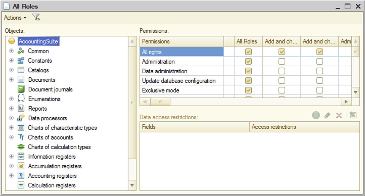
Fig. 65. All Roles Editing Window
The window contains three table boxes. The first (leftmost) field is used to select the required configuration object. The first column of the second table box contains a list of rights for the selected object. The other columns are used to specify use of each right for every existing role.
To set or remove all the rights for any role, select or clear the permission check box in the first row of the table box.
To set or remove all permissions for a certain right in all the roles, select or clear the permission check box in the first row of the table box.
You are allowed to move columns corresponding to roles.
The third table box is used to edit data access conditions at the level of separate fields and records.
5.5.4.8. Data Access Restriction
Overview
Data access restrictions can be used to manage access rights at the level of both metadata objects and 1C:Enterprise database objects. You can use the following 1C:Enterprise objects to restrict access to data:
roles
session parameters
functional options
privileged common modules
ALLOWED keyword in the query language
A combination of the above objects ensures maximum flexibility in assigning data access rights to various users with different job duties.Data access restrictions can be applied to reading or modifying database objects. A current user is granted a right to read or modify a database object only if the applied access restriction entitles him or her to do so. Otherwise the read or modify operation of the database object is not performed.
Various access restrictions can be applied to operations (addition, modification or deletion) with the following types of database objects:
exchange plans
catalogs
documents
charts of characteristic types
charts of accounts
charts of calculation types
business processes
tasks
You can apply restrictions to reading the entire object or its individual fields for the following types of database objects:
exchange plans
catalogs
documents
document journals
charts of characteristic types
charts of accounts
charts of calculation types
information registers
business processes tasks
IMPORTANT!
If you call database object fields from the 1C:Enterprise script using application object properties, it reads the entire object rather than the value of the used field. The only exception is retrieving a presentation when field values are only read if they are a part of this presentation.
Access restrictions are stored in roles, can be assigned to most metadata objects and written in a special language that represents a subset of the query language.
Data access restriction language
Data access restrictions are described in a special language, which is a subset of the query language (for a detailed description of the query language, see page 1-442). Data access restriction language differs from the query language as follows:
A data access restriction query always includes one table as a source of data. This is a table of the object to which such a restriction is applied (the main restriction target).
Query description is shortened. Data access restriction language only uses the FROM and WHERE sections of the query language. For instance, a description in the query language looks as follows:
<Query description>
SELECT  [ALLOWED] [DISTINCT] [TOP <Count>]
<Selection field list>
[FROM  <Source list>]
[WHERE  <Filter condition>]
[GROUP  BY <Group fields>]
[HAVING  <Filter condition>]
[FOR  CHANGE [<List of top level tables>]]
On the other hand, a description in the data access restriction query language looks as follows:
<Query description>
[Main  limitation target table alias]
[FROM  <Source list>]
[WHERE  <Filter condition>]
For a description of a list of sources, see page 1-453. For a description of filter conditions, see page 1-460. Please note that embedded queries used in the data access restriction language have a limited set of available functions (see page 1-191);
Session parameters (see page 1-192) and functional options (see page 1-192) can be specified as condition items;
Templates that simplify a description of restrictions (see page 1-197) may be used in any part of a data access limitation query.
The main component of such a restriction is a condition calculated for each entry of the database table to which a data access restriction is applied. An entry is available if a non-empty table is received when a condition is applied to one table entry of the main restriction target (i.e. a table that contains one or more entries). If an empty table is received when a condition is applied, the entry to which the condition was applied is unavailable. The user can change a table entry for the main restriction target, if such an entry does not contradict the restriction set for the right – both before the change operation, and after it. Table fields
The following can be used in data access limitations:
Table fields of an object, for which data access limitations are described.
For example, if a restriction is applied to reading items of the Contractors catalog, it can use fields of the Contractors catalog and its tabular sections. Thus, the simplest restriction applied to reading items of the Contractors catalog can look like the following:
WHERE Description = "Brickworks"
Or:
WHERE Goods.Description = "Red brick"
Where Goods is a tabular section of the Contractors catalog.
Fields of object tables that can be accessed by references stored in the main object of restriction. For example, if the ChiefManager attribute of the Contractors catalog references the Users catalog, the access restriction can look like the following:
WHERE ChiefManager.Code = "Jones"
Or:
WHERE ChiefManager.Person.Description = "Petrovsky"
Fields of object tables associated with the main object of restriction by certain conditions and expressions with these fields.
For example, you can apply the following restriction to reading items of the Contractors catalog:
Contractors
FROM
Catalog.Contractors  AS Contractors
LEFT  JOIN Catalog.Users AS Users
BY  Contractors.ChiefManager.Description = Users.Description
WHERE  Users.Person.Description = "Petrovsky"
This restriction uses fields of Users catalog items associated with an item in the Contractors catalog by the value of the Description fields. Nested queries
Nested queries are used to create a set of entries to be used:
to connect to a table of the main restriction target; as a comparison operand IN or NOT IN.
Nested queries may use any query language tools except for the following:
IN HIERARCHY operator;
TOTALS statement;
Results of nested queries will not contain any tabular sections; Some virtual tables, including BalanceAndTurnovers.
The next example of a restriction applied to reading the Contractors catalog uses a nested query as a set of records for association with the main object of restriction:
Contractors
FROM
Catalog.Contractors  AS Contractors
LEFT  JOIN
SELECT
Users.Description, Users.Person
FROM
Catalog.Users AS Users
WHERE
Users.Code > "Petechkin") AS  Users
BY  Contractors.ChiefManager.Description = Users.Description
WHERE  Users.Person.Description = "Petrovsky"
Below is an example of a restriction applied to reading the PassportDetailsPersons, where a nested query is used as an operand in the IN comparison operation:
PassportDetailsPersons
WHERE
PassportDetailsPersons.Person  IN
(SELECT DISTINCT
Employees.Person AS Person
FROM
InformationRegister.Employees AS Employees)
If you want to retrieve data from a tabular section in the nested query, you should call this tabular section directly in the FROM section of the nested query. For example, rather than using the following:
SELECT
Ref AS Ref,
Goods.Description AS GoodsDescription
FROM  Catalog.Contractors
as  a query nested in the restriction, you should use the following:
SELECT
Ref AS Ref,
Description AS GoodsDescription
FROM  Catalog.Contractors.Goods
Session parameters
Data access restriction queries may include session parameters. For example, you can apply the following restriction to reading items of the EmailMessageGroups catalog:
WHERE  Owner.AccountAccess.User = &CurrentUser
AND Owner.AccountAccess.Administration = TRUE
Where CurrentUser is a session parameter (see page 1-179).
Functional options
Data access restriction queries may include functional options. You are only allowed to use functional options that are independent of parameters. For example, if the Nomenclature catalog has a MainWarehouse attribute, a restriction applied to reading this attribute might look like the following:
WHERE &AccountingByWarehouse = TRUE
Where AccountingByWarehouse is a functional option (see page 1-211).
Usage features
Restrictions applied to database objects of the following types can only use some fields of the main data object of restriction:
Accumulation registers can contain dimensions of the main restriction object only.
Accounting registers within restrictions can use balance dimensions of the main restriction object only.
NOTE
If turnover register data access restrictions use dimensions that are not part of the totals, then the stored totals will not be used when you are accessing the virtual turnover table, and the request will be based on the record table only.
Access Restriction Actions
Access restrictions are checked every time an operation is performed on database objects (in the dialog boxes, 1C:Enterprise script or queries) and can operate in one of two ways:
All. The "All" approach means that an operation on data (in the dialog boxes, 1C:Enterprise script or queries) should be performed on all database objects the operation includes. If this operation means reading or modifying database objects and the corresponding access restrictions are not met, the operation fails due to access rights violation.
Allowed. With the "Allowed" approach, an operation on data only reads database objects if they meet relevant access restrictions. Database objects that do not meet access restrictions are considered as missing during the operation and have no effect on the result.
Data access restrictions are applied to database objects when 1C:Enterprise calls the database. In the client/server mode of 1C:Enterprise restrictions are applied at the 1C:Enterprise server.
The approach to applying restrictions selected for each operation on data is determined by the purpose of the operation and severity of its results. Thus, the "Allowed" approach is used to display dynamic lists and perform other interactive actions. The "All" option is used to perform all operations on application objects in the 1C:Enterprise script including all changes to database objects. Therefore, it can cause difficulties in generating a selection for the Select() method of catalog, document or other managers with subsequent result iteration if a corresponding object has a relatively complex restriction since some access rights restrictions cannot be represented correctly in a selection for the Select() method.
You can manage the approach to access restrictions in queries. To do so, you can use the ALLOWED keyword of the query language. If a query does not contain ALLOWED, restrictions are assigned the All approach. If ALLOWED is specified, the Allowed approach is applied.
It is important to note that queries with the ALLOWED keyword should only have selections that match all restrictions applied to reading database objects used in the queries. If the query uses virtual tables, the corresponding selections should also be applied to the virtual tables.
Example:
SELECT
ContactInformationSliceFirst.Presentation
FROM  InformationRegister.ContactInformation.SliceLast(, Type = &Type)
AS ContactInformationSliceFirst
WHERE
ContactInformationSliceFirst.Type = &Type
If an object-oriented approach is used, getting access to data in the ALLOWED mode is not supported. Object techniques are intended for critical operations on data including data modification. To retrieve data using object techniques, regardless of the restrictions set, you should perform the required actions in a privileged module or as a user with full access rights. There are no methods of retrieving allowed data only within the object techniques.
Mechanism of Applying Restrictions
In 1C:Enterprise any operation with data stored in the database eventually calls the database requesting to read or modify data. When queries to the database are executed, 1C:Enterprise internal mechanisms restrict access. The following is performed:
A list of rights (read, insert, update, delete), database tables and fields used in the query is generated.
Data access restrictions applied to all rights, tables and fields used in the query are selected in all roles of the current user. If any of the roles has no data access restrictions applied to a table or field, it means values of the required fields are available in any record of the table. In other words, when no data access restrictions are applied, it means the WHERE True restriction.
Current values of all session parameters and functional options that contribute to the selected restrictions are obtained.
To obtain a session parameter value from the current user, you do not need to have the right to obtain this value. However, if any session parameter value has not been set, an error will occur, and a database query will not be executed.
Obtaining functional options depends on the way in which the Privileged mode for obtaining property of the functional option is set (see page 1-211). If the property is reset, the current user will possess read rights for the object where the functional option is stored.
Restrictions retrieved from a single role are grouped using AND. Restrictions retrieved from different roles are grouped using OR.
Generated conditions are added to SQL queries used by 1C:Enterprise to call the DBMS. When data are retrieved (from metadata objects or database objects), access restriction conditions do not validate rights. The mechanism of adding conditions depends on the selected approach to applying restrictions: All or Allowed.
"All" Approach
If restrictions are applied using the "All" approach, conditions and fields are added to SQL queries so that 1C:Enterprise could obtain information on any data in the database query even though it is not allowed for the current user. If restricted data are used, the query fails. An outline of applying restrictions with the help of the "All" approach is shown on fig. 66:

Fig. 66. "All" Approach "Allowed" Approach
If restrictions are applied using the Allowed approach, conditions are added to SQL queries so that records unavailable to the current user have no impact on the query result. In other words, if restrictions are applied using the Allowed approach, records unavailable to the current user are considered missing. An outline of this approach is represented on fig. 67:
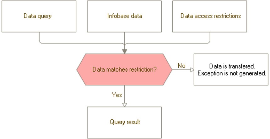
Fig. 67. "Allowed" Approach
Other Objects Associated With Data Access Restrictions
If you develop configurations using data access restrictions, metadata objects, such as session parameters, functional options and common modules with the Privileged flag, might prove useful.
Session Parameters
You can use session parameters in data access restrictions in the same way you use query parameters in queries.
Functional Options
You can use functional options that are independent of parameters in data access restrictions in the same way you use query parameters in queries.
Privileged Common Modules
If a common module has its Privileged flag set, execution of procedures and functions in this module takes on important characteristics:
In 1C:Enterprise client/server mode a privileged module runs at the server only.
When procedures and functions of a privileged module or any objects they call are executed, the rights restriction system is disabled (both for metadata objects and for data). Therefore, in the privileged module, you can perform any operation on any objects even if the current user is not granted the required rights.
Privileged modules are used to set initial values of session parameters used in data access restrictions. Additionally common modules allow users with restricted rights to perform consistent actions with data. For example, if the user is responsible for entering and posting documents, but should have no access to data impacted by document posting, the posting operation can be transferred to a privileged module. In this case the user can post documents without being granted rights to any other data (e.g., registers).
Privileged Mode
When working with data, you can set the privileged mode programmatically. You might need to set the privileged mode programmatically if you perform mass operations with infobase data and do not need to check data access rights. For a description of the privileged mode see page 1-181.
Using preprocessors
Preprocessor instructions can be used when editing data access restriction text. The following instructions are available:
#IF  <Expression> #THEN
#ELSEIF  <Expression> #THEN
#ELSE
#ENDIF
<Expression> – is an arbitrary logical expression in the script with a Boolean type result. The expression may contain the following:
Comparison operations <, >, <=, >= , =, <>.
Logical operations AND, OR, NOT.
Session parameters with syntax &Parameter, where Parameter is the name of the session parameter.
If a #OR or #ELSEIF instruction expression results in True, the resulting text of the access restriction instruction contains the text that follows #THEN keyword. When an expression results in False, the text following #THEN keyword will not be included in the access restriction instruction text. The text following #ELSE will be added to the resulting access limitation text if none of the earlier criteria is met.
NOTE
If the data access limitation text contains preprocessor instructions, the syntax of such a restriction is not checked during editing and cannot be changed via Designer.
Example:
#IF  &CurrentUser <> "Klimova" #THEN
<access  limitation text>
#ENDIF
Where CurrentUser – is a session parameter of type CatalogRef.Users.
This construct means that a condition to set access restrictions will be checked for all users from the catalog, except for Klimova. Access restriction description templates
A role may contain a list of access restriction templates described on the Restriction Templates tab of the role form. Such access restriction templates may be edited in the group editor for access restrictions and templates (see page 1-202).
Every access restriction template has a name and contains text. The template name is compliant with the standard naming conventions for 1C:Enterprise system.
Part of the template text uses data access restriction language. Template text can also contain parameters marked by the "#" character.
The "#" character may be followed by:
One of the following keywords:
□ The Parameter keyword followed by the parameter’s number in the template in brackets;
□ CurrentTable – means the full name of the table for which a restriction is created is inserted into the text;
□ CurrentTableName – means the full name of the table (as a string value, in quotes) to which an instruction is applied is inserted into the text in the current variant of the script;
□ CurrentAccessRightName – contains the name of the right to which the current restriction applies: READ, INSERT, UPDATE, DELETE;
Template parameter name – means inserting a restriction for the corresponding template parameter into the text;
"#" character – means inserting one "#" symbol into the text.
The access restriction expression may contain the following:
Access restriction template in the following format: #TemplateName("Template parameter value 1", "Template parameter value 2", …). Each template parameter is contained in double quotation marks. If the parameter text contain a double quotation mark, two double quotes should be used.
Function StrContains(SearchWhere, SearchWhat). This function is used to search for SearchWhat string occurrences in SearchWhere returns True if occurrences are found, and otherwise False.
"+" operator for string concatenation.
To facilitate template text editing on the Restriction Templates tab in the role form, click the Set the template text button. Type template text in the dialog that opens and press OK.
1C: Enterprise performs a syntax check for the template texts, templates use and macrosubstitution of role access restriction template text in query text.
Template macrosubstitution consists of the following:
replacing parameters’ occurrences in template text with parameter values from the template use expression in restriction text;
replacing the template use expression in query text with the resulting template text.
When a query designer is called for the condition that contains access limitation templates, a warning about replacing all templates is displayed.
Sample restriction templates follow below:
|
Template name |
Template |
|
||||
|
Template body |
Total = #Parameter(1) |
|
||||
|
Usage |
Where #Template("10") |
|
||||
|
Result |
Where Total = 10 |
|
||||
|
Template name |
Template1 (DocumentKind) |
|
||||
|
Template body |
DocumentKind = #DocumentKind |
|
||||
|
Usage |
Where #Template1(""Invoice"") |
|
||||
|
Result |
Where DocumentKind = "Invoice" |
|
||||
|
Template name |
Template2 |
|||||
|
Template body |
DocumentKind = #Parameter(1) ## #Parameter(2) |
|||||
|
Usage |
Where #Template2(""Invoice"", "1"") |
|||||
|
Result |
Where DocumentKind = "Invoice # 1" |
|||||
|
Template name |
Template3 |
|
|||
|
Template body |
DocumentKind = #Parameter(3) |
|
|||
|
Usage |
Where #Template3("","",""Invoice"") |
|
|||
|
Result |
Where DocumentKind = "Invoice" |
|
|||
General Recommendations on Rights Restriction
For flexible control of user access to data and compliance with user duties, you are recommended to use the following guidelines when restricting data access:
Select a set of data (possibly dependent on the current user) that could require preparation. On the one hand, the selected data should streamline data access restriction; on the other, its size should not be too big. Allocate the data by session parameters.
Set values for the session parameters in the SessionParametersSetting() handler of the session module.
Set access restrictions for data that require it the most (data are sensitive or critical to maintaining system integrity). Please note that access restrictions can result in slower handling of these data. Excessively complex restrictions can also affect performance adversely.
If you need to allow a limited set of operations with data for a user who does not need full data access rights, transfer these operations to a privileged module or explicitly enable and disable the privileged mode in the right points of the code (see page 1-181).
When objects are recorded and the system performs appropriate checks, data are accessed in the privileged mode (see page 1-181). In this case you can leave rights restrictions enabled at the level of records for the relevant fields if these data are used in the configuration in the managed mode only:
○ when parent, owner and code uniqueness is checked for catalogs;
○ when code uniqueness is checked for documents, business processes and tasks;
○ when code uniqueness is checked for exchange plans, it is disabled;
○ when parent and code uniqueness is checked for charts of accounts and charts of characteristic types.
When you create a data restriction request, you should note the following:
If data access restrictions are set for the object table and the data access query includes a merge with such a table, connection conditions (the UNTIL query section) can't contain the object tabular section with the set access restriction.
If the query contains a table which does not use any type of field in its query, all data restrictions are applied to the table. For example, the SELECT QUANTITY (*) FROM Catalog.Contractors query will be run with all access restrictions set for the Test catalog. Restrictions are applied as "OR", i.e., all records available by at least one condition will be available. If conditions are not set for some of the fields, the query will be run for all table records.
If the query uses a top-level table, any restrictions set for nested tables columns are not applied.
If the query uses a nested table, all restrictions are applied both for the nested table and the top-level table. For example, the SELECT QUANTITY (*) FROM Catalog.Contractors.Agreements query will be run with all the restrictions for the Contractors catalog and all the restrictions for the Agreements tabular section.
If access to the fields required to get a metadata reference object's representation is disabled using data access restrictions or object access is disabled at the access rights level, then getting the object's representation will not affect the current transaction.
Data Access Restriction Wizard
To open a wizard, in the Access Restriction column in the Data access restrictions table box, click the selection button. Then, in the Restrict access window, click Query Builder.
A wizard form will open:
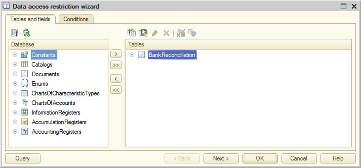
Fig. 68. Tables and Fields Tab in Restrictions Wizard
Use the wizard to specify conditions for data access restriction.
Select the required objects in the Tables and fields tab and move them to the Tables and Fields section. The wizard will also have the Links tab if you specify several tables.

Fig. 69. Links Tab in Restrictions Wizard
The Links tab enables you to specify the criteria for the links between the fields of the tables. Click Add to enter a new condition and select one of the tables from the Table1 column. Select another table with fields linked to the fields of the first table from the Table2 column. Controls that are used to create table link conditions are located below the criteria list.
If a simple type of condition is selected, choose the linked fields of the tables in Field1 and Field2 and set the comparison condition. If the selected fields are not compared, the condition list line will display the following error message in the Link condition column: Incorrectly completed condition.
Specify conditions for source data filtering at the Conditions tab.

Fig. 70. Conditions Tab in Restrictions Wizard
For each selected field, choose the type of condition and specify the parameter name. You can use a session parameter as the parameter. You can specify multiple conditions. In this case the Condition column of the table box displays the condition text in multiple rows.
You can view the query text anytime while generating the query by clicking the Query button.
Batch Editing of Access Rights Restrictions
The batch editing mode for access rights restrictions is enabled by using the All access restrictions command in the context menu of the Roles branch. The form that opens contains two tabs: Access restrictions and Restriction Templates.
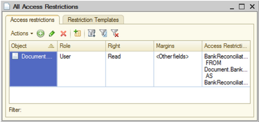
Fig. 71. All Access Rights Restrictions
This mode can be used to view all the entered access restrictions in a single list (by all roles, objects, rights and field combinations).
You are allowed to add access restrictions for multiple roles, objects, rights and field combinations.
You can also filter the lost using different criteria.
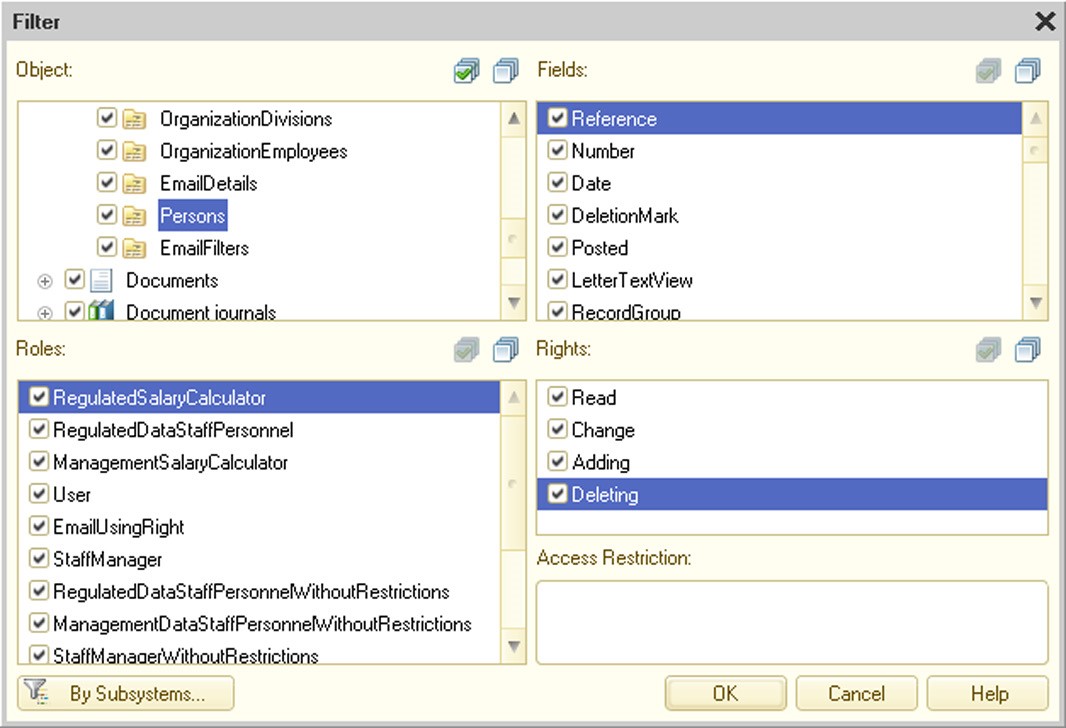
Fig. 72. Filtering Access Restrictions
In the batch editing mode you can remove the restrictions marked in the list.
You can also edit the selected restrictions. While doing so, you can replace a set of fields and/or access restrictions.
Additionally the batch editing mode can be used to copy the selected restrictions to other roles.

Fig. 73. Copying Restrictions
The Restriction Templates tab shows all access restriction templates that are included in the application. But only the first 10 strings ending with ..., if the template text contains more than 10 strings, are shown. The template editing window shows the full template text.
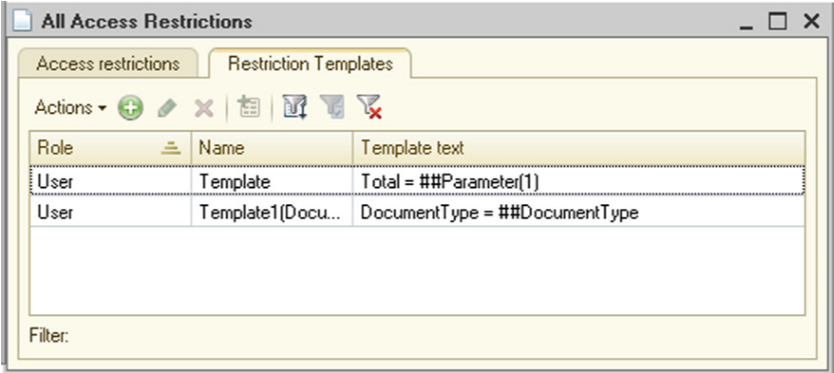
Fig. 74. All Access Restrictions Templates
You can add the access restriction template for multiple simultaneous roles.
You can select the templates you need with a set of criteria and according to the value of the current column.

Fig. 75. Filtering Access Restrictions Templates
If necessary, you can copy one or more templates to other roles.
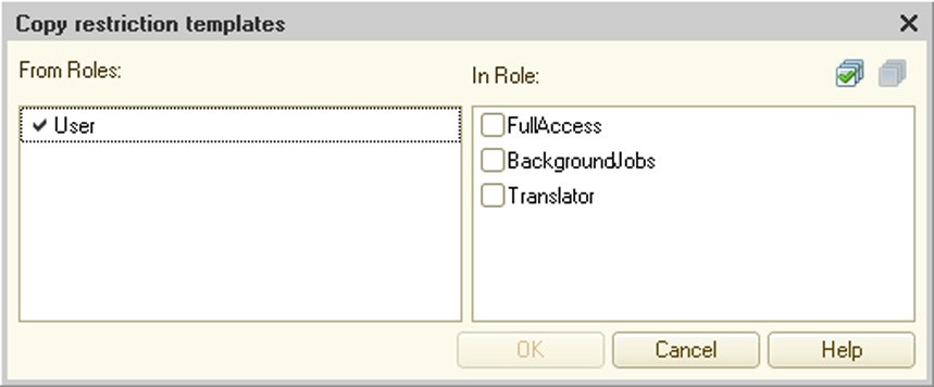
Fig. 76. Copying Restrictions Templates
The editor also allows you to edit selected templates. You are allowed to change the template name and text if needed. 5.5.5. Common Attributes
A common attribute is an attribute that is added to all or multiple configuration objects. A common attribute can be used in two scenarios:
As a common attribute, i.e., to simplify the specification of an attribute that is included in all (or several) configuration objects in which the attribute retains its meaning and type. An example of such a scenario is an arbitrary comment field in application documents.
As a part of data separation – a special application that is used to divide all stored data and application workflow on different parts. Data separation is enabled for the common attribute. An example of this scenario, the subscriber notion is used, when several data "owners" can work in a single physical infobase, while application users will think that the infobase contains only their data. For details on data separation, see page 2-895.
To create a common attribute, you need to create a Common attribute configuration object. You can do this the usual way in the Designer mode, i.e., select Common – Common attributes in the configuration window and add a new object.
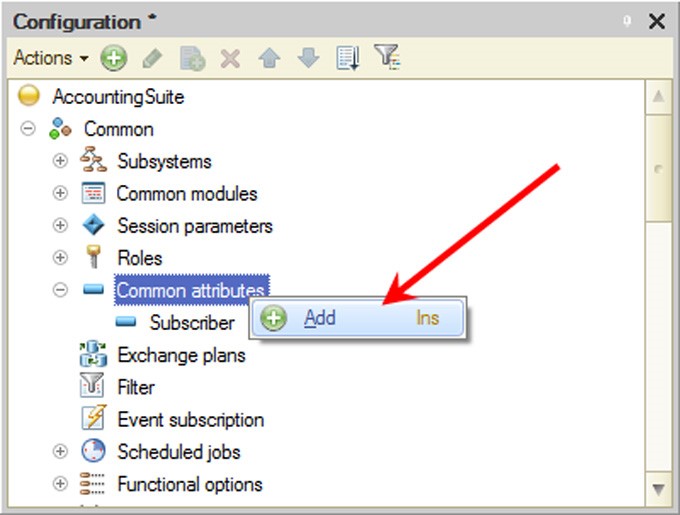
Fig. 77. Creating a common attribute
This will result in a Common attribute configuration object that can be used to include common attributes in necessary configuration objects.
Common attribute behavior is set with the Data split property. If this property is set to Do not use, the configuration object created will be used only as an attribute included in several (or all) of the configuration objects. If the property is set to Split, the common attribute will use a data separator (see page 2-895).
A list of configuration objects in which a common attribute is included is set using the Content and Auto-use properties (or in a corresponding tab in the More window (see page 1-56)).
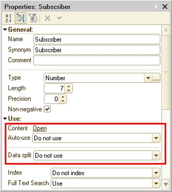
Fig. 78. Common attribute without separation
If the Auto-use property is set to Use, the common attribute created will be automatically added to all existing configuration objects (for which common attributes can be used) and it will be automatically added to all new configuration objects.
If the Auto-use property is set to Do not use, the attribute will not be added automatically, and you should use the Content property to select objects in which common attributes will be included.
The same property should be used when the common attribute is used automatically and there are objects to which the attribute should be added (see fig. 79).
The common attribute content editing window is divided into two parts:
The upper part shows all the configuration objects that can be included in a common attribute.
The lower part shows objects with non-default settings that are set with the Auto-use common attribute value:
○ If the property is set to Use, the lower side will contain a list of objects not included in the common attribute.
○ If the property is set to Do not use, the lower side will contain a list of objects included in the common attribute.
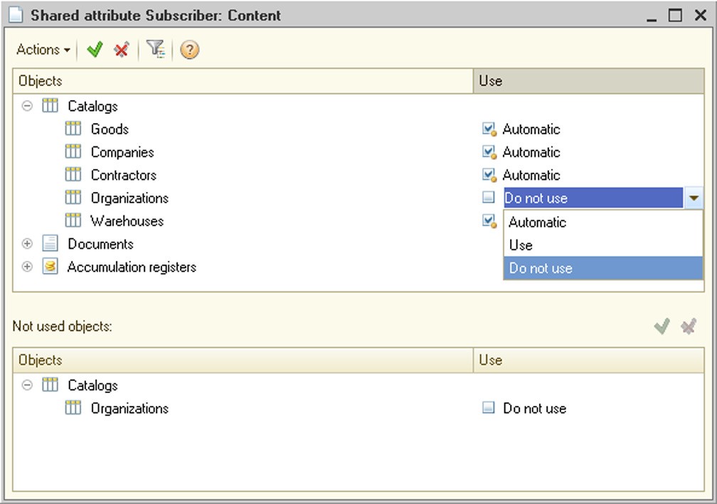
Fig. 79. Common attribute content
You can edit data both in the upper and lower sides, and the edited configuration object will be moved between the window sides regardless of the Use column value.
The Use column can have one of three values for every configuration object:
Automatic – this value means that assigning the configuration object to a common attribute will depend on the common attribute’s Auto-use property:
○ The Use value specifies that the configuration object is included in the common attribute.
○ The Do not use value specifies that the configuration object is not included in the common attribute.
Use – this value specifies that the configuration object is included in the common attribute regardless of the Auto-use property value.
Do not use – this value specifies that the configuration object is not included in the common attribute regardless of the Auto-use property value.
So you can use the Content property, for example, to selectively exclude some objects from a common attribute event if autousage is enabled for the attribute.
A common attribute (without the data separation mode) can include the following configuration objects:
Catalogs
Documents
Document journals
Charts of characteristic types
Charts of accounts
Charts of calculation types
Business processes
Tasks
Information registers
Accumulation registers
Accounting registers
Calculation registers
Exchange plans
External data sources
When a document is recorded, the log’s common attribute gets the value of the document’s common attribute or NULL if the document is not a part of the common attribute.
A common attribute can be used in data access restrictions (see page 1-188).
It is a good idea to add external data sources to the common attribute only if the common attribute is a separator (see page 2-895). Detailed information on how to use an external data source that is part of the separator can be found in the section on this (see page 2-871).
A common attribute can be composite.
TIP
Do not use common attributes to describe data that is related to specific object business logic.
Common attributes are shown in the form editor when you edit common attribute object forms, and they can be placed on a form.
5.5.6. Exchange Plans
Exchange plans are used to implement data exchange procedures. An exchange plan:
Contains information about nodes that can be used in data exchange;
Defines what data are to be exchanged;
Specifies whether the exchange should use the distributed infobase mechanism.
A single application solution can have multiple exchange plans, each of them describing a particular procedure of data exchange. For example, when you exchange data with remote warehouses or offices, you are most likely to use two exchange plans (one for the exchange with warehouses and another – for the offices), since the data set you exchange with the warehouses is much narrower compared to the data set you exchange with the offices.
For a description of data exchange procedures see page 2-745.
5.5.7. Filter
Filter criterion objects are components of the information filtering mechanism. A system configuration specialist uses them to create predefined filtering rules. In the 1C:Enterprise mode these criteria will be used for filtering information from lists.
Specify the name, synonym and comment in the Filter criterion object editing window.
Filter criteria may be of any standard type or of any type defined as configuration tree object. You can include composite-type attributes such as CatalogRef, DocumentRef, etc. and composite-type attributes with a defined chart of characteristic types (Characteristic…).
Specify the types for filtering when you create a type of filter criteria. The Content tab for this type will contain a list of configuration objects containing data of the type that is included in the filter criteria type. Check the attributes that will be used as a filter.
For the criteria to perform their functions, create a list of attributes of catalogs and documents in the Designer (Content tab). There are virtually no limits imposed on the contents of the list: for example, unlike a journal column, you can select several attributes of a document or its tabular section for the filter criteria.
There may be any number of filter criteria and each criterion may have more than one form of displaying results. This procedure can be useful when you look for various information. For example, you want to filter all documents that use a certain contractor (in attributes and tabular sections). You can also set other information filtering criteria (e.g., you can search posted documents only or a specific date range, etc.).
NOTE
When you open a filter form, the Filter parameter with the filter value set (the Value element) will be transferred to it. For more details on the form parameters, see page 1-384.
Filter criterion may have any number of forms for displaying results. For quick retrieval of filtered information you can place the form call in the user menu or on the toolbar.
If there are multiple filter criteria forms, specify the default form in the Default Form property.
If the configuration has multiple subsystems, select the subsystem where the criterion belongs. You can specify several different subsystems.
To call a filter criteria form, the system places the corresponding command in the form navigation panel.
5.5.8. Event Subscription
You can use event subscriptions to assign event handlers for an object or a group of objects in the 1C:Enterprise script.
When you add a new event subscription, in addition to the common configuration object properties you should also specify an event source, an event for the assigned handler and a procedure that handles the event.
Event sources can be application objects and register record sets defined in the configuration. You are allowed to select objects as sources for multiple events or select all objects of the same type (e.g., all documents).
You should select an event in the drop-down list that contains events that are present in all selected objects. Otherwise the list will be empty.
The event handler can be selected in the window containing procedures that can be assigned as event handlers. These procedures should meet the following requirements:
The procedure should be stored in a common module;
The common module containing the procedure should have the following properties set:
○ Global box is unchecked;
○ Client (ordinary application) box is checked;
○ Client (managed application) box is unchecked;
○ Server box is checked;
○ External connection box is checked.
The number of procedure parameters should be one more than the number of parameters for the selected event handler (since in addition to parameters, the event's source object is also passed to the event handler).
When the specified event occurs, the following action sequence is performed:
the event is first processed in the object and calls the handler defined in the object or record set module;
if the handler is performed while the Cancel parameter is set to True or an exception is raised, the action is aborted;
then external event handlers assigned to the event are called in random order;
if the assigned handler is performed while the Cancel parameter is set to True or an exception is raised, the action is aborted.
The object (record set) that has called the event is passed to the assigned handler as a source.
The assigned event handlers are called in the same context as the action that has called the event. If you need to run the assigned handler at the server, you should include a call to the common module procedure performed at the server in the handler code.
You can also assign event handlers by using the 1C:Enterprise script. Use the AddHandler and DeleteHandler operators for these purposes.
Objects that can become sources of events have the AdditionalProperties property of the Structure type. This property can store information between event calls, e.g., information on whether the object is new or old.
5.5.9. Scheduled Jobs
5.5.9.1. Main Features of Jobs
Jobs have the following main features:
Defining scheduled procedures at the stage of system programming;
Performing specified actions in compliance with a schedule;
Calling a specified procedure or function asynchronously, i.e. without waiting its completion;
Monitoring job progress;
Managing jobs (cancelling, locking execution, etc.);
Waiting for completion of a single or multiple jobs.
5.5.9.2. Background Jobs
Background jobs are implemented through the 1C:Enterprise script tools. Background jobs are used to perform application tasks asynchronously. They can generate child background jobs, e.g., to run complex calculations concurrently at different working servers of the cluster in the client/server mode.
You can restrict background jobs with identical methods based on an application characteristic. You can create and manage background jobs programmatically within any user connection to the 1C:Enterprise infobase. A background job is performed under the account of the user that created the job.
5.5.9.3. Scheduled Jobs
Scheduled jobs are an integral part of any application solution. They are described at the configuration stage (see fig. 80).
Each scheduled job can be assigned a schedule that will be used to launch the job automatically. 1C:Enterprise supports one-time and recurring schedules. You can set the start and end date; daily, weekly or monthly schedules. Schedules can be set up both at the configuration stage and at run time (in 1C:Enterprise mode).
When launched, a scheduled job generates a background job that is responsible for the actual processing. A scheduled job can run under the specified user account and can be re-launched (e.g., in case of unexpected shutdown).

Fig. 80. Background Job Schedule
In the client/server mode you can use the administration utility to disable automatic execution of scheduled jobs for a particular infobase.
5.5.9.4. Execution of Scheduled Jobs
In the client/server mode scheduled jobs are launched by the cluster manager. It means scheduled jobs run even if there is no client connection to the infobase (if the jobs are not disabled for this particular infobase).
For peculiarities of background tasks in file and client/server variants, see page 2-831.
5.5.10. Functional Options and Their Parameters
5.5.10.1. Purpose
A developer can use functional options to describe configuration functionality that can be quickly enabled or disabled at the implementation stage or during system operation. For example, you can isolate use of additional merchandise properties as a separate functional option. In this case disabling this functionality hides all functions associated with additional merchandise properties in the configuration interface.
The system can automatically adjust to the modified settings by hiding disabled functionalities and making the interface more transparent and user-friendly.
At the development stage you might want to make a functional option value dependent on specific parameters, e.g., some organizations do not use foreign currency accounting. This can be implemented through Functional option parameters, an object that parameterizes functional options.
5.5.10.2. What Do Functional Options Impact?
Functional options can influence the following:
User interface: If some functional options are disabled, the system hides all associated items of the user interface. The following interface items are affected:
○ Global command interface
○ Form attributes (including attribute columns of ValueTable or ValueTree type)
○ Form commands
○ Reports implemented through the data composition system
IMPORTANT!
If the client application works with a file mode infobase version via a web server, changing the functional option will change the user interface only after the web server restarts (restarting the client application will not change the user interface).
Algorithms written in the 1C:Enterprise script: You can retrieve values of functional options programmatically and use them in various situations, e.g. to decrease the amount of calculation.
IMPORTANT!
Functional options and their parameters do not affect the database structure. All tables and fields remain in the database regardless of the functional options.
Global Command Interface
In the global command interface functional options make the system hide commands for all objects associated with the disabled options. For example, if the Purchases functional option is set to False, it hides commands of opening the Purchases section, creating a GoodsReceipt document, opening a GoodsReceipt list, etc.
At the same time the Purchases option might be dependent on the parameter value of the Organization functional option. Modifying this parameter value in the 1C:Enterprise script, you can change the state of the functional option, i.e. visibility of the interface item.
The following should be considered when creating the command interface:
The command will be excluded from the command interface if the functional option has disabled the attribute which is a parameter of that command.
The command will be excluded from the command interface if the functional option has disabled the command parameter type. If the command parameter type is a compound one, the command will become unavailable when all parameter types are disabled.
Form
Functional options can affect form attributes and commands, as a consequence, changing visibility of associated form elements (fields and columns for form attributes and buttons for form commands). Please take note of the following system behavior features when developing a form:
The form attribute of the reference type will be disabled if the functional option disables the configuration object forming this type. The complex type form attribute will be disabled if the functional options disable all complex types.
The <Type>Object form attribute (e.g., the main form attribute) will be disabled if the functional option disables the configuration object forming this type.
The form table will be disabled if it displays the data of a form attribute disabled by a functional option.
Types are not available in the type selection dialog (e.g. for text boxes linked with complex type attributes) if the functional option disables configuration objects forming this type. Information regarding the types disabled by functional options is cashed on the client side and cleared in 20 minutes or when the RefreshInterface() method is called.
IMPORTANT!
Unlike the command interface, parameter values of functional options are set for a specific form instance only.
Data Composition System
The data composition system is mainly used to generate reports. Functional options affect data sets output in the report and the list of report settings available to the user. For example, if the Foreign currency accounting functional option is disabled, the report outputting a Goods Receipt document register will not contain Currency and Currency amount columns and filtering, grouping, sorting and performing other actions based on the Currency field will not be available.
For details on how functional options affect availability of fields in a report generated in the data composition system, see page 1-633.
Characteristics
Functional options affect the visibility of form fields that display object characteristic values. To make such changes, you need to add an attribute with a characteristic value to a functional option.
Consider the following example. Characteristics are used for the Products catalog, characteristic types are stored in the plan as Characteristics and their values are stored as a CharacteristicValues information register resource. A resource is included in the CharacteristicsAccounting functional option.
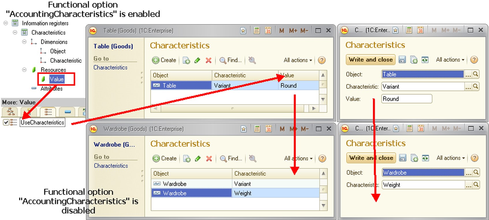
Fig. 81. Influence of functional options on characteristics
If you disable the CharacteristicsAccounting functional option, field visibility is disabled in forms (the Value column and Value field), thus displaying characteristic values as shown in fig. 81.
5.5.10.3. General Workflow
Use of functional options involves two metadata object types: Functional option and Functional option parameters.
A functional option is a metadata object that can directly influence the application interface (if the option stores its value in a Boolean type attribute). You can use objects of this type to hide items associated with unavailable functionality. For example, the Multicurrency accounting can hide the Currencies catalog, the Currency field in documents or the Currency amount in reports. The source of the functional option value is a metadata object selected as the Location property; it can be a constant, for example.
If a functional option value is stored in a catalog attribute or an information register resource, additional information is required to specify the exact way of selecting the option value. This is where the Functional option parameters metadata object is used.
Functional option parameters can be compared to axes of reference in a space of functional option values. A single parameter of functional options can define its own axis value for a subset of functional options.
Consider the following example. Assume that the sum total depends on a warehouse owned by a particular organization (see fig. 82). The infobase can maintain accounting for various organizations at multiple warehouses.
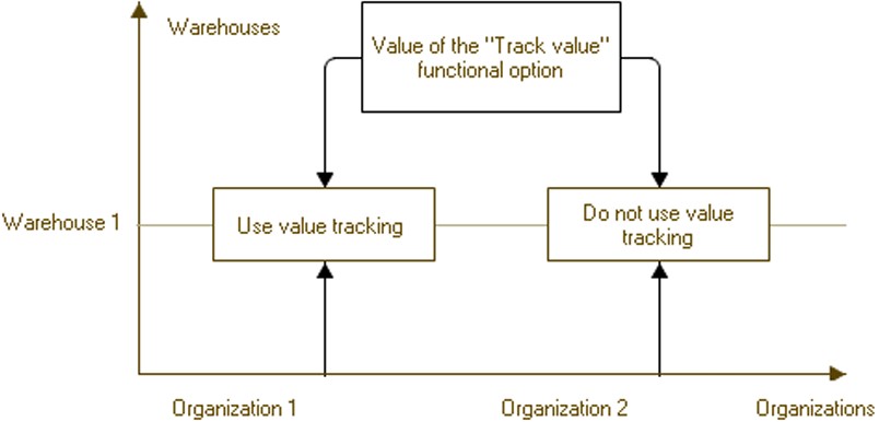
Fig. 82. Parameterized Functional Option
To store values of functional options, create an information register with the following dimensions (axes of reference): Organization (of appropriate type), Warehouse (of appropriate type).
A resource of the information register will be a value of a quantitative accounting functional option.
Then the general configuration structure will look like the following:
Information register SumTotal: ○ Organization dimension;
○ Warehouse dimension;
○ SumTotal resource of Boolean type.
Organization functional option parameter. The Use property references the Organization dimension of the SumTotal information register.
Warehouse functional option parameter. The Use property references the Warehouse dimension of the SumTotal information register.
SumTotal functional option, Location property references the SumTotal resource of the SumTotal information register.
As a result, if you want to define whether quantitative accounting is required, you need to specify values for functional option parameters (Organization and Warehouse) in each particular case and retrieve values of functional options.
Thus, in the example on, sum total is allowed for Organization 1 and Warehouse 1, but is not allowed for Organization 2 and Warehouse 1.
5.5.10.4. Interaction with Other Objects
Functional options can be assigned to the following configuration options:
subsystems
common commands
constants
filter criteria
catalog
document
journal
chart of accounts
chart of characteristic types
chart of calculation types
business process
task
exchange plans
report
data processor
accumulation register
information register
accounting register
calculation register
command
metadata object attribute
tabular section
tabular section attribute
accounting flag
extra dimension accounting flag
addressing attributes
register dimension
register resource
Functional options can also affect visibility of form elements.
5.5.10.5. Creation
Creation of Functional Options
To create a functional option, you need to create a Functional option configuration object. You can do it the usual way in the Designer mode, i.e. select Common – Functional options in the configuration window and add a new object (see fig. 83).
It will result in a Functional option configuration object that can be used to assign functional options to other metadata objects (see fig. 84).
In addition to the name field, the object has another required field – Location. In the editor you can select one of the objects that will serve as a source for the option value. The list of available objects includes:
Constants
Catalog attributes
Information register resources
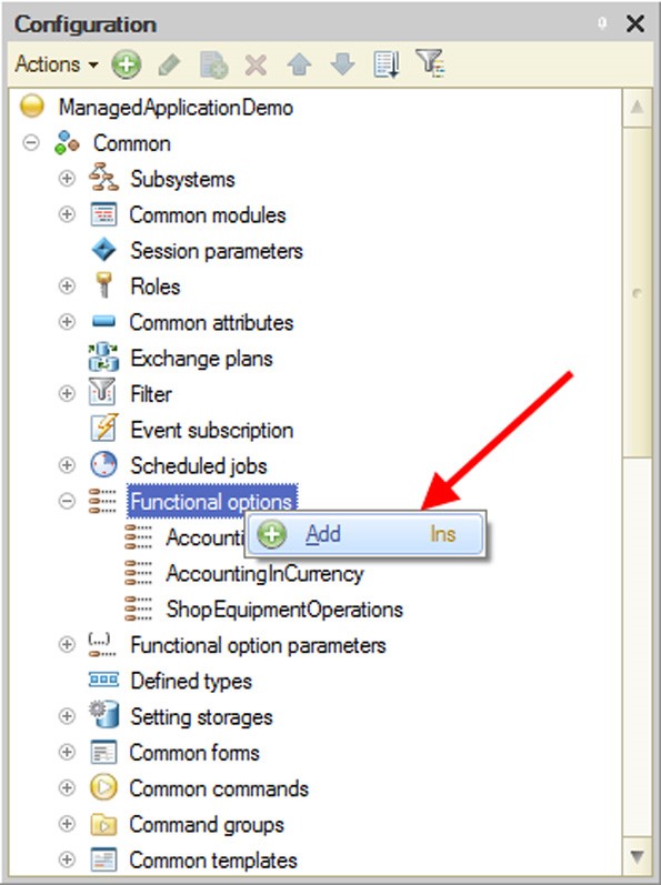
Fig. 83. Creating a Functional Option
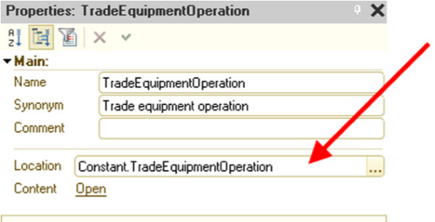
Fig. 84. Location of Functional Option Value
The source of the option value can be any type, without restriction; however, for interface management purposes you can only use functional options that store their values in attributes of the Boolean type. Functional option values of other types are only available for analysis in the 1C:Enterprise script.
The PrivilegedGetMode property specifies how the functional option value is received (and cached).
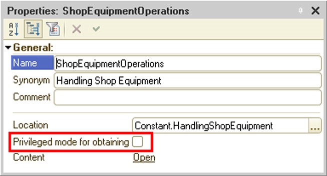
Fig. 85. Privileged mode when getting the functional option value
If this property is set, the functional option value is performed in privileged mode. The received value is cached for all sessions related to this infobase.
If the PrivilegedGetMode property is reset, the functional option value is performed in normal mode. Caching is performed for the current session. Both the value (if it was received) and the flag indicating that the value can't be received are cached.
The cache is reset if the session parameter values are changed.
TIP
Setting the PrivilegedGetMode property is recommended in all cases when a functional option value does not contain sensitive information.
Creation of Functional Option Parameter
To create a functional option parameter, you need to create a Functional option parameter configuration object. You can do it the usual way in the Designer mode, i.e. select Common – Functional option parameters in the configuration window and add a new object.
In addition to its name, the object has another required property – Use. This property indicates a set of objects that define how a functional option value is selected. The list of available objects includes catalogs and information register dimensions. You can select a catalog (out of the entire catalog list) and a dimension in each information register for every functional option parameter on the list.
IMPORTANT!
You cannot use the same metadata object in multiple functional option parameters.
5.5.10.6. Use
Assignment to Metadata Objects
A metadata object (e.g., a catalog) can be assigned to one or more functional options. To do so, you can use the Functional options property that stores references to the functional options created in the configuration (see fig. 86).
The list of available options is limited to the options that have an object of Boolean type in their Location property.
IMPORTANT!
If an object is not assigned any functional options, it is always visible. Otherwise the object is visible if at least one of its assigned functional options is enabled (i.e. functional options are grouped by OR).

Fig. 86. Assigning a Functional Option to an Object
Assignment to Form Attributes and Commands
Objects that belong to a form (Attributes and Commands) can also be used in functional options.

Fig. 87. Assigning a Functional Option to a Command
You can do so in the form editor by setting the Functional options property for the required object.
The state of functional options affects visibility of form objects in the same way it affects metadata objects. For example, if a command is disabled using a functional option, all associated buttons are hidden.
If a form attribute or command has no functional options assigned, it is always visible. Otherwise the form attribute or command is visible if at least one of its assigned functional options is enabled. Use in Data Access Restriction
You can use Functional options within data access restrictions (see page 1-188) in the same way as Session parameters (see page 1-179). You are only allowed to use options that are independent of parameters, i.e. are bound to constants.
IMPORTANT!
The system checks name uniqueness for session parameters and functional options.
Definition of Functional Option Value
A functional option value is defined by the object indicated in the Location property. With constants, their values are used. With options that are associated with catalog attributes or information register resources, values stored in these objects are used. To find the specific object that stores the functional value parameter, you need additional information – a set of parameter values for functional options.
If an option is stored in a catalog attribute, the parameter should reference this attribute. If an option is stored in an information register resource, values for all register dimensions should be specified. In this case each dimension should be characterized by its own parameter.
If some parameters are missing for a functional option of Boolean type, all values with unspecified parameters are grouped by OR. For example, if a functional option is stored in an information register with Organization and Warehouse dimensions, but you only set the Organization dimension, the functional option value is set to True if at least one warehouse listed in the Warehouse dimension has a functional option value set to True.
However, if a functional option type is different from Boolean and some parameters are not specified, it raises an exception.
Methods of the 1C:Enterprise script allow you to retrieve an option value depending on the passed parameters and for the parameters set for the command interface or a specific form.
If a functional option is bound to a resource of a periodic information register, the system uses the Slice Last to retrieve the option value. If you want to retrieve an option value for a different date, you should specify a value for the Period parameter of Date type that is then used as a date for slice retrieval. You do not need to create this parameter in metadata. It is automatically provided by the system.
When using parameterized functional options, you should keep in mind the following:
In list forms an attribute column associated with the parameterized functional option is displayed if the infobase stores and least one enabled value for this functional option.
If you want all attributes associated with functional options to be disabled by default when you open a form, you should set values of these parameters to those missing in the infobase (an empty reference for catalogs or values of dimensions with no records for information registers). In this case the functional option is set to False.
If a reference to a group (if the type of a functional option parameter allows group creation) instead of a reference to an element is specified as the parameter, the system will behave as follows:
○ If an attribute that stores a functional option value is used both for the element and the group, the value of the functional option will be defined by the value of this attribute.
○ If an attribute that stores a functional option value is not used for a group, NULL is returned when a functional option value is obtained with the following methods: GetFunctionalOption(), GetFormFunctionalOption(), and GetInterfaceFunctionalOption(). If a functional option that has been parametrized impacts the user interface, the system will perceive it as disabled (the functional option will be set to False).
You can set a snap to a parameterized functional option for metadata objects used as a basis for commands. Commands for these objects are only displayed in the command interface if there is at least one combination of functional option parameters that makes the functional option value True. However, you can use the SetInterfaceFunctionalOptionParameters() method to set specific parameter values for functional options. In this case command visibility is defined by the parameters you specify.
A dynamic list automatically uses functional options used by the form. If the attributes used in the dynamic list query are disabled for the specified combination of functional option parameters, the corresponding data are not selected and displayed in the dynamic list and the attribute is removed from the lists of available attributes in the Dynamic List Data Display Settings dialog box (in 1C:Enterprise mode).
5.5.10.7. Use of Functional Options in 1C:Enterprise Script
Global context methods GetFunctionalOption() and GetInterfa- ceFunctionalOption() return a functional option value. The difference is that the first method allows you to specify a set of functional option parameters, while the second method returns a functional option value depending on the parameters specified for the command interface.
Forms have their own method that returns an option value for parameters specified within a particular form – GetFormFunctionalOption().
If a functional option value changes in the database, the global command interface and currently open forms are not automatically updated.
To update the global command interface, you should explicitly call SetIn- terfaceFunctionalOptionParameters(). The command interface is updated with regard to the new state of the functional options.
NOTE
If a functional option value changes in the database, the global command interface and any currently open forms are not automatically updated. You should use the RefreshInterface() method after writing the functional option values to the database.
Note that setting functional options parameters (and running the RefreshIn- terface() method) have the following consequences:
For every form closing of all auxiliary forms is called (and the corresponding handlers are called).
Forms that are denied closing are not closed.
Main form elements are refreshed.
If the main form was active at the moment of interface refresh, the main form is shown with new elements.
If an auxiliary form was active at the moment of interface refresh, then:
○ the open auxiliary form command will be executed, if this is available when the interface is refreshed.
○ otherwise, the main form elements are refreshed and the form is displayed.
If an auxiliary form opened with a command that is not related to the form navigation panel was active at the moment of interface refresh, the main form elements will be updated instead and the main form will be shown.
To refresh a specific form you should reopen the form or call the SetFormFunctionalOptionParameters() method. The steps above will work only for the form, in the context of which form setting the functional option parameters was initiated.
You do not need to specify all parameters at once; you can change a value for a specific parameter or a set of parameters. However, setting a group of values in a single call is more efficient.
To retrieve parameter values, you should call an appropriate function (GetInterfaceFunctionalOptionParameters() or GetFormFunctionalOp-
tionParameters()) that returns the specified parameters as a structure with the parameter name used as a key.
When opened, the form automatically uses parameters of the functional options set for the command interface.
5.5.11. Defined types
A defined type is a special configuration object for defining a type of data for a frequently used entity, or there is high probability that it will change when an application is implemented. A generic subsystem used to store contact information may be used as an example. This subsystem includes an information register that stores this information. This register contains a dimension that specifies the object for which such contact information is stored. A contractor, owner organization, physical entity, etc. can be used as a dimension value. A type (named Cata- logOfOrganizationsAndIndividuals) that describes this storage object does not necessarily have to be a register dimension type. The contents of this type may be changed in the process of application implementation: new catalogs may be added and the types that are no longer required may be excluded. If a composite type is used instead of the CatalogOfOrganizationsAndIndividuals type, in each instance where such an entity is used the contents of types will have to be changed everywhere. It is complicated, and there is always a chance that an attribute with the required composite type will be forgotten. If a composite type is used, it is only necessary to edit the composite type definition in the application customization process (and, of course, all application code fragments that use this type). All attributes that have the CatalogOfOrganizationsAndIndividuals type specified as their type will be changed automatically.
A defined type is characterized by the following:
It can be a composite type.
It cannot be part of a chart of characteristic types value type.
It cannot be part of a composite data type of another attribute.
To describe a type with a script, use the DefinableType.<NameOfDefi- nedType> construct.
NOTE
If you need to use an application with 1C:Enterprise legacy versions (under 8.3.3), delete all definable types from the configuration.
5.5.12. Settings Storages
To save information about user settings that need to be saved between the sessions, the platform offers you settings storages.
There are two types of settings storages:
Standard storage is used by the system by default and stores data in system tables of the infobase.
Settings storages are special metadata objects that describe how data are stored in an infobase object. For example, this object could describe how to work with settings stored in a catalog.
The platform uses the following storages:
System storage is a storage where the system stores all settings required to operate the platform. These settings include settings of form sizes, print settings of spreadsheet documents, etc. For a complete list of settings stored in the system storage, see page 2-1199. A standard settings storage is always used as a system settings storage. It means that data from the system storage are always saved in the system table of the infobase.
Common settings storage is used to store various application settings. The platform does not write any settings to the storage independently. A developer should use this storage in the 1C:Enterprise script, to save or restore user application settings.
Reports user settings storage contains reports user settings.
Reports variants storage stores report variants.
Form data settings storage stores form data. You can use this storage to save data processor attributes, for example. Please note that you can select a different storage for each report or data processor.
Dynamic list user settings storage is a storage system for storing the user settings of dynamic lists.
When developing a configuration, you can define custom settings storages of all types, except the system storage. To do this, create a settings storage object in the appropriate branch of the metadata tree and then select it in the required configuration property. Properties of the Configuration object have the same names as the storages listed above.
Storage data can be stored in either the infobase system table or a special infobase object, e.g., a catalog or an information register. For example, you can create a settings storage object in the configuration and use a configuration property to indicate that this storage stores report settings. It means that report settings are saved in an object, e.g. a catalog, rather than in the system table. In this case you can use common report settings or implement a system of rights and exchange of settings, etc.
A custom storage makes sense when you need to create a special structure to store settings or special procedures of settings management or else arrange settings exchange inside the distributed database (see page 2-745) and in other similar cases.
NOTE
It is recommended to save settings in objects that support an identification method in which the identifying attribute can be converted into a string and backwards with no data loss. An example would be a catalog and the standard Code attribute that is unique in the entire catalog.
5.5.12.1. General Principles of Settings Storage Operation
SettingsStorage metadata object is used to store application settings of the configuration. By implementing event handlers and creating object forms, you can change the way you work with the settings, i.e. modify the storage location (use developer-generated configuration objects instead of system tables) and visual mechanisms of working with the settings.
Any number of settings storages can be defined in a single configuration.
Settings storages can be used for both the programmed operations and programmed and interactive operations. In the first case the required functionality is provided through mandatory implementation of the SettingsStorage object module by the handler:
SaveProcessing contains an implementation of the Save() method.
This handler has to save a setting in an object, e.g. a catalog item.
LoadProcessing contains an implementation of the Load() method.
This handler has to retrieve settings from an object, e.g. a catalog item.
IMPORTANT!
If a required handler is not implemented, the action it performs is unavailable. For example, if you do not implement the SaveProcessing handler, you cannot save settings.
When developing a storage, the developer determines how the storage object is identified, thus defining the parameter type. For example, if settings are saved in a catalog, you can use the Code field or the Ref value (of a catalog item) as the setting key.
If you want to work with the settings interactively (use forms to save and restore the settings), you need to implement these forms and fill in the corresponding properties of the SettingsStorage object (Save form and Load form).
IMPORTANT!
Implementation of forms for saving and restoring settings is mandatory for interactive operations. You can also save and restore settings programmatically without implementing these forms.
When a user chooses to save or load the settings, the system gets a corresponding form for the settings storage object and displays it on the screen. For example, when you save report settings, the system uses a form to save a metadata object selected as the report settings storage (for a particular report or the entire configuration). The parameters passed to the form are described in more detail in a description of the SettingsDescription object in the Syntax Assistant.
If a form is created through a wizard, the required parameters are automatically added to the list of form parameters.
Forms should use the passed parameters and filter the settings list appropriately. Thus, you should only display the settings for the setup object (e.g. a report) specified in the ObjectKey parameter.
If you select a setting, the result of the form activities should be a value of the SettingsSelection type. The SettingsKey of this value must contain a key for the selecting setting (e.g., a catalog item code or another parameter that identifies the setting), while the AdditionalProperties property should store additional information possibly specified in the form by the user:
Close(New SettingsSelection(SavedSettingKey));
IMPORTANT!
A setting cannot be saved in the standard settings storage if the object key length exceeds 256 characters or the settings key is more than 128 characters long, or the user name has more than 64 characters.
5.5.12.2. Creation of Metadata Object
If you want to create a Settings storage, create a configuration object with the same name. You can do it in the Common branch by selecting the Settings storages item.
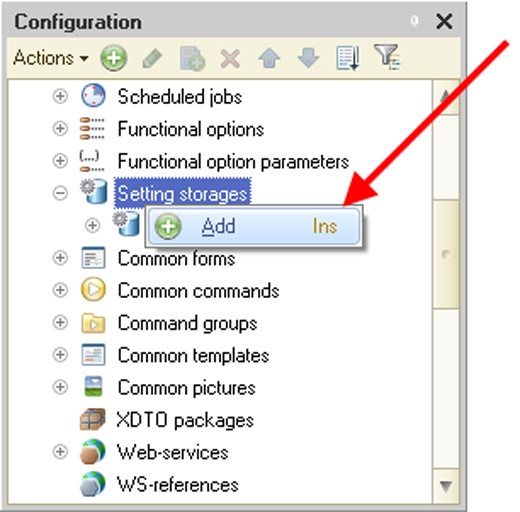
Fig. 88. Creating a Settings Storage
5.5.12.3. Standard Settings Storage
In the 1C:Enterprise script a standard settings storage is represented by the StandardSettingsStorageManager object. Having the same set of methods as the SettingsStorageManager object, this object also implements the following additional methods:
GetList() – a method that retrieves a list of settings for the selected settings object;
Delete() – a method that deletes a specific setting of the selected settings object.
The standard storage save settings in the system tables of the infobase.
The system settings storage takes a string as a settings object key and a setting key.
It also takes any values that can be placed into a value storage as settings.
NOTE
When you use the Save(), Delete() and SetDescription() methods of the StandardSettingsStorageManager object, note that if the object to which settings are related (e.g., a form) has already been used in the current session, changes will be applied only in the next session.
TIP
If you significantly change settings programmatically (for example, when you copy the settings of one user to another user), it is recommended to prompt the users to restart the client application.
5.5.12.4. How to Save Form Settings
A developer can control how form data are saved in the settings. The following form properties should be used for this purpose when developing a form:
Save form data in the settings: This property helps the form developer enable a functionality to save form data (a setting where data are saved can be selected). If a form has its save functionality enabled, it makes available commands for saving or loading settings.
Autosave form data in the settings: This property indicates settings are to be auto-saved when the form is closed and restored when the form is opened. It is irrelevant whether the settings list is used or not.
If data saving is enabled in the form, you need to specify what form attributes are to be saved (Save column at the Attributes tab of the form editor).
When settings are save, the full form name is used as an object key. An object of the Map type is saved in the settings. It stores paths to the saved attributes as keys and attribute values as values.
5.5.12.5. How to Save Report Settings
Report and external report objects have the following metadata properties: Variants repository and Report variants storage. These properties indicate what storages should be used to save report variants and settings, accordingly. If the storages are not specified, storages indicated in the configuration properties are used. If configuration properties do not indicate specific SettingsStorage objects either, the system storage is used.
A report form contains commands for saving and loading report variants and settings.
If you need to save additional information in data composition settings or data composition user settings, you can use AdditionalProperties properties of the DataCompositionSettings and DataCompositionUserSettings objects. The AdditionalProperties property is an object of Structure type.
5.5.12.6. Storing dynamic list settings
The user settings of dynamic lists are stored in the storage specified in configuration properties (DynamicListsUserSettingsStorage). If configuration properties do not specify a settings storage, the system storage is used.
The Auto save user settings property of an attribute that refers to a form of type DynamicList controls the function to automatically save the user settings of a dynamic list. If the property is set to True, user settings are automatically saved when the form is closed and are loaded when it is opened.
A dynamic list form provides the user settings save and load commands. A dynamic list also provides a command to specify standard settings. If this command is executed, the dynamic list will include settings from property List.SettingsComposer.Settings.
The OnUpdateUserSettingSetAtServer event can be called for a dynamic list in the following cases:
When a dynamic list form is opened.
When the user settings editing is concluded (if the settings have been changed).
5.5.12.7. Settings Storage Development Procedure
Below is a recommended procedure of developing a settings storage:
1. Determine the type of storage to be used (see the beginning of the section). For example, you want to implement a settings storage for configuration form data.
2. Make a list of metadata objects that will use the storage and a list of data to be stored, define the data structure and types. This information helps you select an appropriate metadata object to store the settings.
3. Use information from step 2 to create an object (and its structure) for storing settings. Let us assume the settings will be stored in catalog items. Since in this case the structure of data to be saved is heterogeneous, it is inconvenient to implement separate sets of attributes to store settings from each form; therefore, the settings will be stored in a catalog attribute of ValueStorage type.
4. Create an object of ValueStorage type and implement save and load forms for it. This ensures you can use interactive operations when saving and restoring the settings.
5. Implement event handlers associated with saving and restoring the settings for the newly created ValueStorage object. If you do not perform this action, settings read/write operations will fail. To solve this issue, implement SaveProcessing and LoadProcessing event handlers in the module of the newly created ValueStorage object.
6. The objects selected at step 2 (or in the configuration properties) have their properties filled in, thus indicating what storages will be used to save the settings. In this example you need to fill in the Form data settings storage configuration property with a reference to the object created at step 4.
7. Events handlers associated with saving and restoring settings in application objects are implemented, if necessary.
5.5.12.8. Working with Settings Storage from the Script
This example reviews how the current user’s settings can be copied by other users of the system. SystemSettingsStorage is used as a source of settings.
NOTE
The example below is not complete. It simply demonstrates how to work with standard settings storage.
A list of user names is transferred as an array with the help of the CopySettings() procedure parameter.
Procedure  CopySettings(ListOfUsers)

SettingsDescription = New SettingsDescription;
SettingsSelection = SystemSettingsStorage.Choose();
While SettingsSelection.Next() Do

For Each User From ListOfUsers Do

SettingsDescription.Presentation =  SettingsSelection.Presentation;
SettingsStorage.Save(SettingsSelection.ObjectKey,
SettingsSelection.SettingsKey,  SettingsSelection.Settings, SettingsDescription, User);

EndDo;

EndDo;

EndProcedure
5.5.13. Common Forms
The common forms mechanism makes it possible to use forms accessible from any module of the current configuration. For details on how the form editor works see page 2-937.
If you want to include a command that would open a common form in the command interface, you can do this by using the Use standard commands property.
The command opening a common form will be included in the command interface of the subsystems that own the common form.
If a common form is included in a functional option and the option is disabled, the common form standard command will not be shown in the command interface.
If you create a common form that will be used as a report form, a report or variant settings, setting the Use standard commands property for this form is not recommended.
5.5.14. Common Commands
A developer can use this branch to create commands that are not object-specific and are used to perform actions on objects which do not use standard commands.
For a description of the command interface see page 1-83. For a description of commands see page 1-266.
5.5.15. Command Groups
A developer can use this branch to create custom command groups. Location of the created group in the command interface is defined by the command Group property. A command group can be located:
In the navigation panel
In the form navigation panel
In the actions panel
In the form command bar
For a description of the command interface see page 1-83. For a description of commands see page 1-266.
5.5.16. Common Templates
The common templates mechanism (print forms, report forms, references, etc.) can be used to create print form templates accessible from any module of the current configuration.
For details on how the spreadsheet document editor works see page 2-996.
5.5.17. Common Pictures
The Designer makes it possible to use graphic images or pictures in a configuration. Pictures may be used in some controls, forms and templates. They may also be called using the 1C:Enterprise script.
If a picture is used as an icon in a menu, toolbar, spreadsheet document, etc., it is important to specify proper dimensions for the picture so that it displays correctly.
The following picture sizes are recommended:
Max 16x16 pixels for icons
Max 14x14 pixels for table boxes
Max 9x9 pixels for pictures of an edit field selection button
Max 48x48 pixels for pictures used as subsystem presentations
TIP
If a picture is to be used in several places, its size should be as small as possible.
Use the Configuration Picture Library window to work with pictures. Select Common pictures in the Configuration window and then select All Images from the context menu.
The picture list maintenance window will open (see fig. 89).
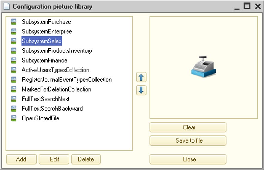
Fig. 89. Picture Library
To add a new picture, press the Add button. A new window will open, where you can select a picture from a file or open the picture editor and create a new picture. You can also use this window to select or change the transparent background for a picture. To select an existing picture, press the Select from file button and select the file containing the existing picture. In the 1C:Enterprise system, you can use BMP, GIF, JPEG, PNG and TIFF picture formats, as well as icons and metafiles (WMF, EMF).
TIP
For pictures used as interface icons (for the recommended picture sizes, see the beginning of the section), it is recommended to use formats that support lossless compression (PNG and GIF), prevent distortion and minimize client/server traffic.
Specify the name that will be used to select this picture by means of the 1C:Enterprise script.
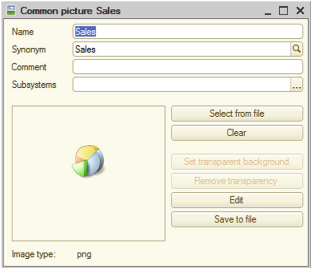
Fig. 90. Picture Properties
It is recommended to use transparent background for a picture to fit well into a control or a form. To do this, when editing the picture select any color that is not used in the picture as a background color, create an image and save the picture. You can specify any color for an existing picture. If the color is transparent, you can see components of the form that are covered by the picture.
To set a transparent background, click the Set transparent background button. The mouse cursor will change its appearance. Move it to the component of the picture that you want to make transparent and left-click it. The selected color becomes transparent.
To remove transparency, click the Remove transparency button.
The Set transparent background and Remove transparency buttons are only available for the following picture formats: BMP, JPEG and TIFF. They are not available for pictures of other formats.
You can also perform similar actions using the Select link in the Picture property. The picture selection window will open.
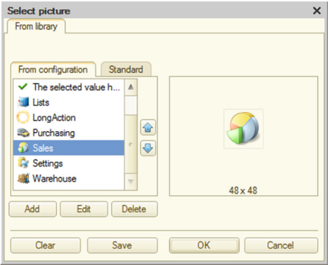
Fig. 91. Picture Selection
Click the Edit button to edit the picture. The picture editor will open (for details see page 2-1012).
5.5.18. XDTO Packages
The XDTO mechanism is a universal data presentation method that interacts with various external data sources and software systems. For details on how to use the XDTO mechanism see page 2-789.
5.5.18.1. Import of XML Schemas Into XDTO Global Factory
In order to import an XML schema from an .xsd file into the XDTO global factory, select the XDTO branch in the configuration tree and click Import XML Schema in the context menu.
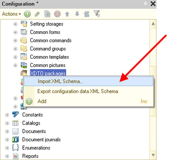
Fig. 92. Import XML Schema
Once the required .xsd file has been specified, the availability of the XDTO packages must be checked in the configuration tree, with the namespaces matching those imported from the file. If these packages are available, a list will be displayed and you will be prompted to specify the packages to be updated (the existing packages are not updated by default).

Fig. 93. Namespace Selection
The import procedure is then executed, resulting in the addition of new XDTO packages to the configuration tree, while packages specified for update will be updated.
5.5.18.2. Export of Configuration XML Data Schemas
To export an XML schema corresponding to configuration data types (without consideration of the XDTO packages created in the configuration tree) to an .xsd file, specify the XDTO branch in the configuration tree and execute the Export configuration data XML Schema command in the context menu.
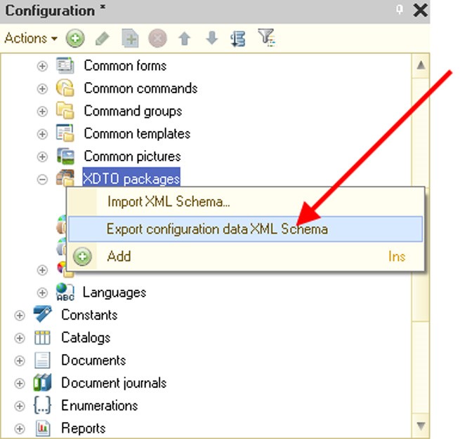
Fig. 94. Export of Configuration Schema
Once the directory has been selected and the file name specified, the XML schema is exported to the specified file.
5.5.18.3. Export of XDTO Package XML Schema
To export an XML schema corresponding to the existing XDTO package to an .xsd file, select the relevant XDTO package in the configuration tree and click Export XML Schema in the context menu (see fig. 95).
The dumped XDTO package will be checked. If any errors are detected, the relevant messages will be displayed in the message window and the export procedure will be interrupted.
If the check is successful, you will be prompted to choose the directory and .xsd file name and then the XML schema will be exported to the specified file.

Fig. 95. Export of XDTO Package XML Schema
5.5.18.4. Check of XDTO Packages
To check an XDTO package, specify the relevant XDTO package in the configuration tree and execute the Validate package command in the context menu.
As a result, the XDTO package model will be checked (for a description of check rules see page 2-808).
If any errors are detected, the relevant messages will be displayed in the message window.
5.5.18.5. XDTO Package Editing Window
XDTO packages can be edited in the XDTO package editing window.
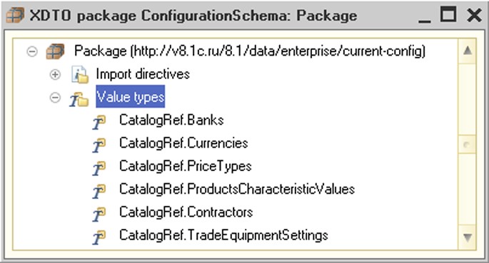
Fig. 96. XDTO Package Editing Window
When a new XDTO package is added to the configuration tree, the XDTO package editing window opens automatically.
To open the editing window for an existing XDTO package, specify the relevant XDTO package in the configuration tree and execute the Open package command in the context menu.
XDTO Package Hierarchical Structure
The XDTO package editing window contains the hierarchical tree of the XDTO package.
The XDTO package ID containing the corresponding namespace URI is located at the tree's root.
The first hierarchy level can include the following package elements:
Import directives – a list of import directives. An import directive is a reference to another package containing the types referenced by this package. When you are using the 1C:Enterprise script to work with this XDTO package, this list of import directives will be available as a XDTOPackageCollection object stored in the Dependencies property of the XDTO package;
Value types – a list of XDTO value types stored in the XDTO package.
Object types – a list of XDTO object types stored in the XDTO package.
Properties – a list of XDTO package properties. It represents declarations of objects/values that can be the root items of XML documents, belonging to the namespace URI of this XDTO package.
Each XDTO value type is described by the hierarchical structure and can contain the following items:
○ Pattern describes one XDTO facet of the Pattern type.
○ Enumeration describes one XDTO facet of the Enum type.
Each XDTO object type is described by the hierarchical structure which can contain a set of object properties.
XDTO Package Properties
XDTO package properties are edited in the properties palette.
If the properties palette is open for an XDTO package specified in the configuration tree, it will contain the following properties: Name, Synonym, Comment, Subsystems and Namespace URI. In addition, the properties palette will contain the Package reference which can be used to switch to the XDTO package editing window (see fig. 97).
If the properties palette is open for the XDTO package specified in the XDTO package editing window (root item), it will only contain the Namespace URI property. This property defines the namespace URI for the XDTO package which owns all types defined in this package.
Fig. 97. XDTO Package Properties
Import Directive Properties
Import directive properties are edited in the properties palette. For import directives, the properties palette only contains the Namespace property. This property sets the namespace URI for the imported package.
Fig. 98. Import Directive Properties
XDTO Value Type Properties
XDTO value type properties are edited in the properties palette.
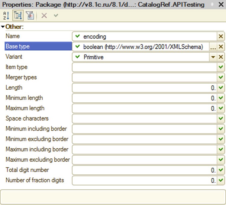
Fig. 99. XDTO Value Properties
For XDTO value types, the properties palette contains the following properties:
Name – a name of the type for a XDTO value;
Base type – a base type for this type of XDTO value;
Variant – a simple type variant (primitive type, list, union). If a value is set, it has to match the Item Type and Union Types values;
Item type – a list item type in cases where the XDTO value type is defined by the list. All facets and Types of Subordinates must be null;
Merger types – a list of types making up a union, in cases where the XDTO value type is defined by a union. Only XDTO value types can become unions. All facets and the Item Type property must be null;
Length – the length facet;
Minimum length – minimum length facet;
Maximum length – maximum length facet;
Space characters – white space facet;
Minimum including border – facet of the minimum, including limit;
Minimum excluding border – facet of the minimum, excluding limit;
Maximum including border – facet of the maximum, including limit;
Maximum excluding border – facet of the maximum, excluding limit;
Total digit number – facet of the total number of digits;
Number of fraction digits – facet of the number of fraction digits. XDTO Object Type Properties
XDTO object type properties are edited in the properties palette.
Fig. 100. XDTO Object Properties
For XDTO object types, the properties palette contains the following properties:
Name – a name of the XDTO object type.
Base type – a base type for this XDTO object type. It can only be an XDTO object type.
Open – this flag specifies if the XDTO object type is open. This property indicates whether the XDTO object instance can contain additional properties not defined in its type.
Abstract – this flag specifies if the XDTO object type is abstract.
Mixed – this property indicates whether the corresponding XDTO object contains mixed contents. If the Mixed property is set to True, then the Sequenced value will always be True, because mixed contents cannot be modeled without using an XDTO sequence.
Ordered – this flag specifies if the order of items that represent property values strictly corresponds to the order of properties in the XDTO object type. If the Ordered property is set to False, then the input sequence order of XML elements is not controlled and the output is defined by the sequence order of properties, provided that the value of the Sequenced property is not True.
Sequenced – this property shows if an instance of the relevant XDTO object contains an XDTO sequence. This flag has the True value in those cases where the sequence order of the nested XML elements cannot be unequivocally defined by the sequence order of the properties in the type or the relevant XDTO object has mixed contents. Use the XDTO sequence to expressly set the order of items in the way they are represented in the XML document. The order of the nested items corresponds to the order of properties for objects of the types, for which the Sequenced property is set to False. Properties of XDTO Object Type Properties
Properties of XDTO object type properties are edited in the properties palette.

Fig. 101. XDTO Type Properties Palette
For XDTO object types, the properties palette contains the following properties:
Name – a property name. Property names should be unique within a single XDTO object type;
Type – a property type. It can be both a XDTO value type and XDTO object type;
Minimum number – a minimal number of property values. The minimal number of property values can take values >= 0. Naturally, the Minimum number value must be less than or equal to the Maximum number value (provided that the Maximum number is not equal to -1);
Maximum number – properties of the XDTO object type can be defined as containing single or multiple values. A property is considered to contain a single value if the Maximum number property is equal to 1. If the value of the Maximum number property is greater than 1, it is considered that this property can contain multiple values. These properties are modeled as lists in the object structure. The Maximum number property shows the maximum number of property values. Maximum number > 1 can be set only for properties represented in XML element form;
Can be empty – indicates whether the property can take an Undefined value. The Can be empty property equal to True can be defined only for properties with the Item form of representation. If Maximum number > 1, an Undefined value is allowed for the property values list item;
Fixed – specifies if the property value is fixed. If this is set to True, the fixed value itself can be obtained through the Default property;
Default – a default property value. The default value type can only be a XDTO value type. In terms of types, this value must be compatible with the property type (i.e. be of the same type as the property or of the inherited type). If a single value is allowed for the property when an XDTO object is created, it takes the default value. For properties with multiple values, a list of values is initially empty, irrespective of the fact that the default value is defined;
Form – is the form of property presentation in XML. It can be Text, Item or Attribute. If the form of presentation is Attribute or Text, the value of the Maximum number property cannot exceed 1. If the property has the Text value, then the value of the Minimum number property will also be equal to 1. Only one property of a separate type can have its form of presentation set to Text, while all other properties must have their form of presentation set to Attribute;
Local name – a local name used for property presentation. For properties with the Text presentation form it is an empty string.
Global Property
Properties of a global property are edited in the properties palette (see fig. 102).
The properties palette for a global property contains the following properties:
Name – a global property name. Global property names should be unique within a single XDTO object type.
Reference – a reference to a root definition of a package property.
Type – a global property type.
Minimum number – a minimal number of property values. If Minimum number is 0, the property value might not be set.
Maximum number – a maximum number of property values. If Maximum number is -1, the number of property values is unlimited.
Can be empty – indicates whether the property can take an Undefined value.
Fixed – specifies if the property value is fixed.
Default – a default property value. The lexical representation of the property value must follow the rules of the property type check.
Form – is the form of property presentation in XML. It can be Text, Item or Attribute.
Local name – a local name used for property presentation.
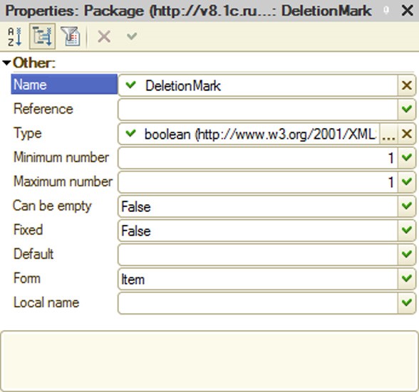
Fig. 102. Properties Palette for a Global Property
5.5.19. Web-services
The Web service mechanism allows to use 1C:Enterprise as a set of services in complex distributed and heterogeneous systems, as well as integrate it with other industrial systems using the service-oriented architecture. For details on how to use the Web service mechanism see page 2-819.
5.5.19.1. Addition of Web Services
To add a Web service to the configuration tree, select Common – Web-services and click Add in the context menu.
This command opens a Web service editing window (see page 1-59).
Specify the following parameters at the Other tab of the Web service editing window:
Namespace URI – contains URI of the Web service namespace. Each Web service can be uniquely identified by its name and the URI of the namespace to which it belongs;
XDTO packages – a list of XDTO packages with the types that can be used as returned value types for operations and parameter types of Web service operations;
Publishing file name – a name of the Web service description file located at the Web server (for details on Web service publication see "1C:Enterprise 8.3. Administrator Guide").
To get access to a web service, you need to use the address in the following format: <Web server host name>/<Virtual directory name>/ws/<Web service name> or <Web server host name>/<Virtual directory name>/ws/<Web service address>.
So if a virtual directory is named DemoWS, the web service is named DemoOperationWS in the Designer while the address is DemoWorkWS, and this web service can be accessed using two addresses simultaneously (from a local machine): http:// localhost/DemoWS/ws/DemoOperationWS or http://localhost/DemoWS/ws/DemoWorkWS.
The tab also contains the Module button that opens a Web service module for editing.
5.5.19.2. Web Service Hierarchical Structure
Every Web service described in the configuration tree can contain a set of operations. Each operation must have a corresponding export procedure, described in the Web service module.

Fig. 103. Web Service Description
Additionally each operation can contain a set of parameters with names corresponding to the names of the procedure parameters describing this operation.
5.5.19.3. Web Service Operations
Use the Operations tab to add Web service operations. Use the properties palette to edit the operation properties.
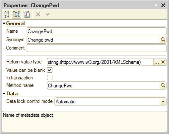
Fig. 104. Web Service Operation Property
Return value type – a value type returned by the Web service operation. It can be an XDTO value type or XDTO object type.
Value can be blank – indicates whether the returned value can have an undefined value.
In transactioned – indicates whether or not the code of the Web service module will be executed in the transaction. If the property is set, the transaction will start automatically when the Web service is called and upon completion, the transaction will be either submitted or rolled back (depending on the results of execution). If the property is not set, the transaction is not started when Web service module execution starts.
Method name – a name of the Web service module procedure that will be executed when this property is called.
5.5.19.4. Operation Parameters
Use the Operations tab to specify parameters for a Web service operation. Use the properties palette to edit the parameter properties (see fig. 105).
Value type – a value type of the Web service operation parameter. It can be an XDTO value type or XDTO object type.
Value can be blank – indicates whether the operation parameter value can take an undefined value.
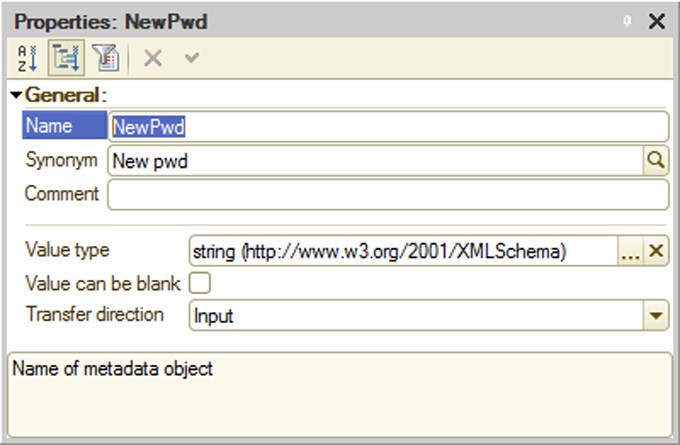
Fig. 105. Operation Parameter Properties
Transfer direction – defines the direction of data transfer using this parameter. Available values:
Input – means that the parameter can be used for data transfer to the Web service only;
Output – means that the parameter can be used for both transfer and retrieval of data to/from the Web service.
5.5.19.5. Selection of System-Defined Types
If you want to use types defined by the 1C:Enterprise system in the Web services (e.g., in the parameters and values returned by the operations), you need to define XDTO packages in the configuration and specify a set of platform packages that contain these types, in the relevant lists of imported packages (the Import directives property). You can find namespace URI to specify a particular type in the relevant article on an object of this type in the Syntax Assistant.
5.5.19.6. Web Service Publication
Web service publication is described in "1C:Enterprise 8.3. Administrator Guide".
5.5.20. WS-references
1C:Enterprise can use third-party Web services by using static references created in the configuration tree.
5.5.20.1. Addition of WS References
To add a static reference to an external Web service to the configuration tree, select the WS reference branch and click Add in the context menu or the Actions menu.
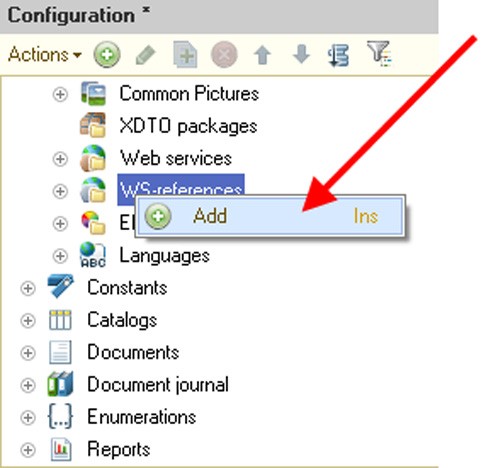
Fig. 106. Adding a WS Reference
You should type the URL of the added Web service description in the opened window, e.g. http://users.v8.1c.ru/ws/products.1cws?wsdl.
NOTE
When you add a WS reference, note that 1C:Enterprise deletes the final character "/" from the URL entered. 1C:Enterprise therefore considers the URL http://localhost/ws/ws-service/?wsdl and the URL http://localhost/ws/ws-service?wsdl to be identical.
5.5.20.2. WS Reference Hierarchical Structure
The hierarchical structure of a WS reference can be viewed in the WS reference viewing window. Values of the reference element properties can be viewed in the properties palette.
In order to open the WS reference viewing window, select the required WS reference in the configuration tree and click Properties in the context menu. Then use the WS-reference property in the properties palette to open the WS reference viewing window.
Fig. 107. WS Reference
The viewing window contains the hierarchical structure of the WS reference, displayed as a tree.
The first hierarchy level can include the following elements:
Data model – contains a list of XDTO packages describing the structure of the types used by the Web services to which this WS reference refers;
Web-services – a list of Web services to which this reference refers.
You can view data model structure and properties in the same way as you view XDTO packages (see page 1-236); however, you cannot edit properties of packages displayed in the WS reference viewing window.
You can view WS reference structure in the same way as you view Web services; however, each Web service has a list of supported connection points that also have a list of operations and their parameters.

Fig. 108. Web Service Structure
Using different Web service connection points allows you to run operations using different protocols.
5.5.21. Style Elements
Style elements configuration objects are used to ensure consistency in formatting various form elements in cases where 1C:Enterprise automatic formatting is not sufficient. For example, you might want to highlight labels in configuration forms using the same color. In this case it is convenient to create a style item, assign it a color and use the created item to set the text color for a form element.

Fig. 109. Using Style Items
Style elements can be of three types:
Color
Font
Border
NOTE
System style items cannot be selected as values of custom style items.
The font selection dialog box used at the thin client contains a list of fonts that includes fonts installed at the machine and special fonts enclosed in angle brackets (<>). If you select <Font>, the system will use a font of the 1C:Enterprise interface, while all other fonts will correspond to the fonts existing in the operating system. A list of <Font> sizes starts with "<>". Selecting this font size (its value is 0) means that the font size will match that of the 1C:Enterprise interface. The font effects (bold, italic, etc.) default to the style settings, but can be customized without any limitations. If you select another font, all changes to the font size and effects are reset to the default values.
You can access the style item value programmatically, using the Value property.
Example:
Metadata.StyleItems.NegativeColor.Value
5.5.22. Languages
Languages configuration objects are used to create program interfaces in different languages. Each configuration object of the Languages type has a separate reserved string for the metadata attributes that can be represented in different languages.
Let us review a sample form for the Items catalog item. For the Russian language the form labels look like the following:
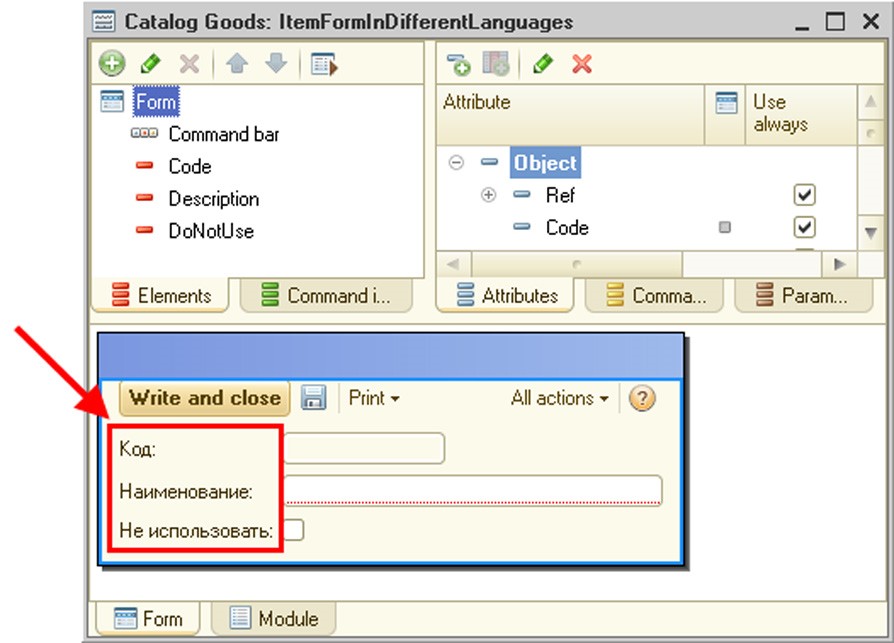
Fig. 110. Form in Russian
If the Languages branch contains more than one object (e.g., Russian and English) and you want to change the language, select Configuration – Design Language. Select the configuration viewing language in the opened language selection window.
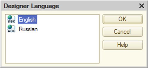
Fig. 111. Selection of Designer Language
The same can be done using the language selection button located on the status bar to the right of the CAP and NUM buttons (the right bottom corner of the main Designer window).
The Designer replaces label text with the text in the selected language.
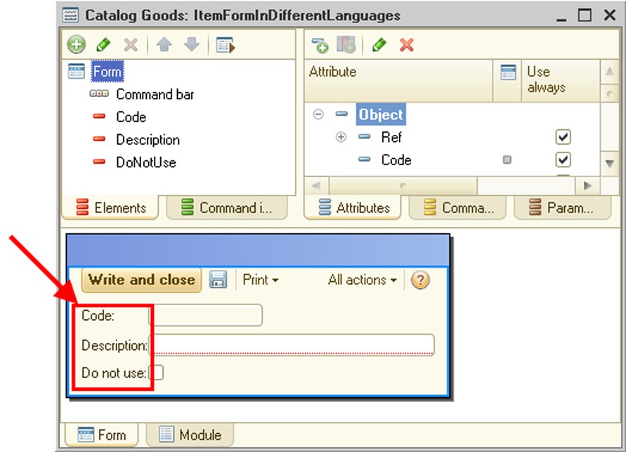
Fig. 112. Form in English
Of course, the label text has to be entered in advance for each control. To enter the text in the properties palette of the Label control, click the magnifier button in the Title property (Text or Synonym, depending on the type of control), see fig. 113. The Strings in Different Languages window will open.
TIP
A configuration can have any number of languages. However, there is no need to create Languages objects "just in case", since they may be created at any time.
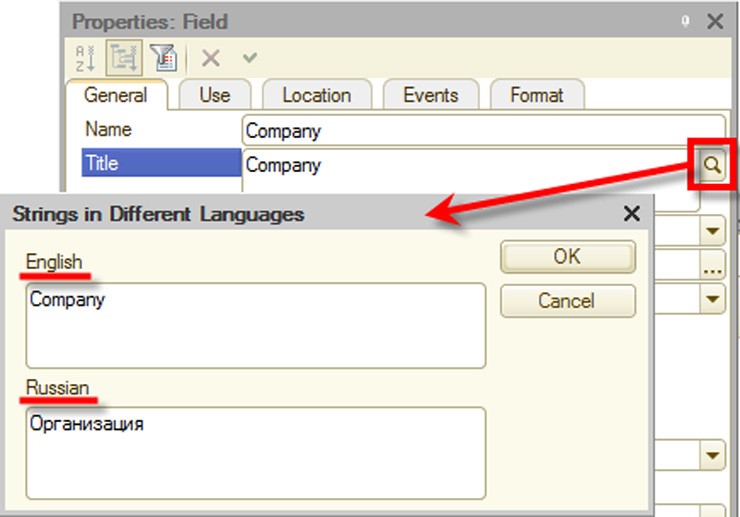
Fig. 113. Strings in Different Languages
Language code property contains the language code, e.g., EN for English.
If two or more Languages objects are defined in the configuration, the text editing button (a magnifier icon) will be displayed for the Synonym and Title properties of the control.
The first language object is created by the system according to the language (country) selection for a new infobase.
To create a text representation of an attribute to be displayed in the form, the following rules are used:
The title of the displayed object is retrieved in the configuration language of the current user. If the title is specified, it is the one that is used.
The system attempts to retrieve the synonym of the displayed object in the configuration language of the current user. If the synonym is specified, it is the one that is used.
Subsequent actions depend on the type of the displayed object:
○ For standard attributes, a representation in the platform localization language is retrieved;
○ For objects created by the application developer, the object name is used as it is specified in the configuration (including its language).
IMPORTANT!
If the language code in the Language code property is changed, texts in the Synonym or Title properties will be "lost" (they will be stored for the previous code value). The texts will be "restored" when the previous code value is specified.
For the purpose of text editing and localization (creating an interface in a different language), use the Edit interface texts mode (see page 2-1021).
If the application is to be used on mobile devices, language codes shall be specified as per ISO 639 (http://www.iso.org/iso/home/standards/language_codes.htm). Otherwise, a warning will be displayed during the configuration check.
5.6. COMMON PROPERTIES OF CONFIGURATION OBJECTS
This section describes common properties of configuration objects.
5.6.1. General Properties
Most configuration objects have the following properties which appear in the General category:
Name: The name of the configuration object. The name must consist of a single word, begin with a letter and contain no special characters other than underscore ("_"). The 1C:Enterprise script tools access and manage configuration object by its name. Names of configuration objects must not be identical to the reserved words of a query language (see page 1-445 for a list of reserved words).
Synonym: In addition to the name, you can also specify a synonym. If the configuration is to be used in different languages, synonyms in the languages used should be specified. When working with the 1C:Enterprise system, a synonym will be displayed in various selection lists, window titles and label texts, when interfaces are generated, taking the current language into account. A synonym has no restrictions on the use of characters. If no synonym is specified, the name is selected.
NOTE
The name or synonym displayed to the user are also called the presentation of the configuration object.
Comment: An arbitrary character string. As a rule, it's drilled down and explains the name of an object. When shown in various lists (for example, in the list of catalogs for selection of the desired catalog), a comment is shown in parentheses immediately after the presentation of the configuration object.
5.6.2. Metadata Object Presentation
Various object presentations are allowed for many configuration objects. This functionality allows the developer to set a presentation of standard commands, their tooltips and form titles.
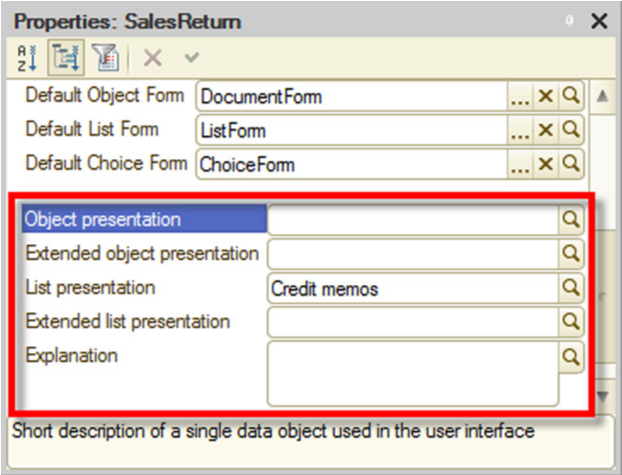 Fig. 114. Object
Presentation
Fig. 114. Object
Presentation
Object presentation (for a register – Record presentation):
○ An object name (e.g., Account).
○ This is used in a standard command presentation (creation of an object).
Extended object presentation (for a register – Extended record presentation) is used to generate a title for the object form. For example, Organization account.
List presentation:
○ A name for a list of objects (e.g., Accounts).
○ This is used in a standard command presentation (a command that opens an object list).
Extended list presentation is used to generate a title for the list form (e.g. Organization accounts).
Extended presentation – a title of a report or data processor form (e.g., Report on mutual settlement of accounts).
Explanation is used to generate tooltips for standard commands (e.g., Accounts of my organizations).
Picture – a picture that represents a subsystem in the sections panel.
Please note that you only need to fill in the properties associated with the object and list presentations if you want to specify more information in addition to the data displayed by default.
For example, you have a Goods catalog (Name of the metadata object is Goods, Synonym of the metadata object is Goods) that can contain goods and services as its items. However you want to use singular in command texts ("Create product") and do not want to include services data as it makes commands longer. At the same time, you want to show the user that the relevant object form can be used to edit both goods and services. In this case you can enter Product text in the Object presentation property and Product (service) in the Extended presentation property. Then the command for creating a Goods catalog item will look like Product: Create, while the form will have a Product (service) title.
For details on which of the above properties belong to particular metadata objects see page 2-1195. You can also read about the rules of generating texts for standard commands, command tooltips and form titles.
5.6.3. Custom Presentation of Data
The standard data presentation provided by the system may be unacceptable for the user. This can happen, for example, when the system is operated by users speaking different languages and system objects contain all the necessary information in different languages as well. For instance, let the products have two names: in Russian and English. But the text should be displayed depending on the session localization code. In addition, the presentation should be generated in the required language in every location where the object presentation is formed: in a dynamic list, report, etc.
To implement this, the developer can use a special feature which allows him to define the attributes involved in generating the presentation and to describe an algorithm based on which the object presentation will be generated.
This is available for the following configuration objects:
Exchange plans
Catalogs
Documents
Charts of characteristic types
Charts of accounts
Charts of calculation types
Business processes
Tasks
Tables of external data sources
The presentation is created in two steps: defining the attributes involved in generating the presentation and then generating the presentation itself.
The attribute list is defined through the PresentationFieldsGetProcessing event handler in the respective object manager. The handler is called during the first attempt to get the presentation of a selected object, and the result is saved for the current session. Names of attributes that will be involved in generating the presentation should be specified in the Fields array of this handler. If the StandardProcessing parameter in the handler is set to the True value, then after the handler completes its operation, the Fields array will be cleared and filled with the fields used to create a standard presentation of this object. If not, the system will only use the values put into the Field array.
NOTE
The examples below are not complete. They simply illustrate how to work with custom presentations.
For instance, the Goods catalog has the following attributes: RussianDescription, EnglishDescription and Article that are to be used in generating a presentation. In this case the handler of the getting presentation fields (in the Goods catalog manager module) will look as follows:
Procedure  PresentationFieldsGetProcessing(Fields, StandardProcessing)

Fields.Add("RussianDescription");
Fields.Add("EnglishDescription");
Fields.Add("Article");
StandardProcessing = False;

EndProcedure
When it is necessary to get a presentation, the system calls the PresentationGetProcessing event handler in the respective object manager. The values of the attributes involved in generating the presentation are passed to this handler.
The program code located in this handler generates a presentation text.
CAUTION!
The PresentationGetProcessing event handler is called whenever the presentation of any infobase object is required. Redundant data or incorrect data selection for generating the presentation can significantly slow down system operation.
The PresentationGetProcessing event handler creates the presentation and returns it via the Presentation handler parameter. The data required to generate the presentation is passed through the Data parameter. The Data parameter is a structure where the key is the attribute name and the value is the value of the attribute for the current object. If the StandardProcessing parameter is set to True, the system will attempt to generate a standard presentation for the current object based on data passed. In case the Data parameter contains no attribute required to generate a standard presentation, then the presentation will be an empty string.
Let us review a sample creation of a presentation for the Goods bilingual catalog.
Procedure  PresentationGetProcessing(Data, Presentation, StandardProcessing)

StandardProcessing = False;
SessionLocaleCode = Upper(CurrentLocaleCode());
If Find(SessionLocaleCode, "RU") <> 0 Then
Text = Data.RussianDescription;
ElseIf Find(SessionLocaleCode, "EN") <> 0 Then
Text = Data.EnglishDescription;
Else
Text = Data.RussianDescription;
EndIf;
Presentation = Text + "(" + Data.Article +  ")";

EndProcedure
Please note that a 1C:Enterprise script error in the PresentationGetProcessing handler may sometimes lead to abnormal termination of application.
5.6.4. Standard Attributes
If you need to override interface properties (such as a synonym, fill checking, etc.) for standard attributes (e.g., Code, Description, Parent) and standard tabular sections (e.g., ExtDimensionTypes, BaseCalculationTypes) of application objects at the configuration level, you can set up these properties.
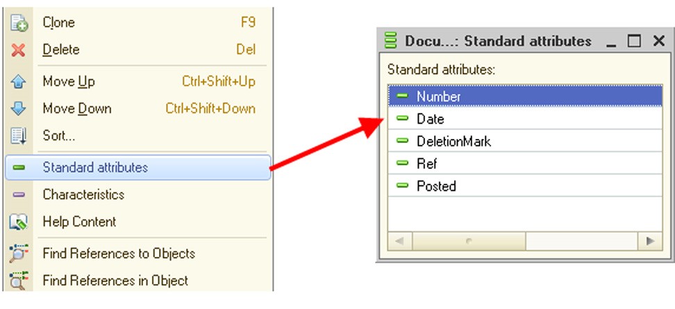
Fig. 115. Standard Attributes
To do this, you can use commands that open lists of standard attributes and tabular sections in the properties palettes of certain objects (see fig. 115). These commands are available for the objects that own standard attributes and tabular sections.
You can use the properties palette to override some properties of standard attributes so that they fully meet the requirements of the application task at hand. For example, you can set Contractor as a synonym for the Owner property of the Accounts catalog. Then this attribute (Owner) will be represented as "Contractor:" in all forms by default.
If properties of a standard attribute or tabular section are not specified, default properties of standard attributes are used instead.
A standard attribute has virtually the same set of properties as any other attribute; however, you cannot modify the following:
The standard attribute name
The standard attribute type
The standard tabular section name
The standard attribute indexing
IMPORTANT!
If a standard attribute has a description, its name remains unchanged, i.e. it does not change calls to the attribute from the 1C:Enterprise script and the query language.
5.6.5. Predefined data
5.6.5.1. Overview
Predefined data means the items of application objects created in Designer. They can be called directly by name, without a preliminary search required. If a certain data element will be constantly needed and will require simple access from program code, this serves as a reason to create predefined data. For instance, the predefined element Service can be created in the Goods catalog. To call this element, execute Catalogs.Goods.Service. Individual elements and groups of elements may be predefined. Groups can be created if predefined elements are created in hierarchical objects, such as a hierarchical catalog. Predefined data can be created:
For catalogs (see page 1-280)
For charts of accounts (see page 1-652)
For charts of characteristic types (see page 1-309)
For charts of calculation types (see page 1-665)
When a predefined element is created in Designer, the possibility to create or update the data elements related to it is defined by a combination of the following two values:
Configuration object property value PredefinedDataUpdate. Is set in Designer;
Object property value in the infobase. Use 1C:Enterprise mode and methods GetPredefinedDataUpdate() and SetPredefinedDataUpdate () to obtain and set the value for this property.
The property can have three values:
Do not update automatically: in this case the system does not create or update a data element when predefined data is created or modified. However, it should be noted that if such a property is set for a configuration object, an exception may be generated when predefined data is called since a data element connected with a predefined element is absent;
Update automatically: in this case, the system automatically creates new data elements (or updates the existing ones) for new (or changed) predefined data;
Auto: the system defines the need for an update automatically. No update is performed in the following cases:
○ If the configuration object properties (metadata) have the Predefi- nedDataUpdate property set to Do not update automatically; the value set in 1C:Enterprise mode is irrelevant.
○ If the configuration object properties (metadata) have the Predefi- nedDataUpdate property set to Update automatically, and Do not update automatically is set via method SetPredefinedDataUpdate().
○ If Auto is set in the metadata and 1C:Enterprise mode, and the action is executed in the subordinate node of a distributed infobase (see page 2-772).
The action to be taken by the system is defined via the AND operation between a configuration object property and a property of an object specified in 1C:Enterprise mode. It should be remembered that Auto values do not participate in defining an action (create or do not create). First, they are resolved into one of two values: Do not update automatically or Update automatically, and these values are then used in the AND operation.
A data element is connected to a predefined data element via PredefinedDataName. This property facilitates the following:
Connecting a predefined data element with a data element. To do this, assign the name of a predefined data element to be connected with data to the PredefinedDataName property:
ItemRef  = Catalog.Goods.FindByDescription("Delivery service ");
Object  = ItemRef.GetObject();
Object.PredefinedDataName  = "Service";
Object.Write();
This operation maps a predefined Service item of the Goods catalog to a data item named Delivery service.
When an object is written, the system checks that an infobase contains no other data element with exactly the same name as this predefined element and set to the value with which the data element is written.
"Disconnect" a data element from a predefined data element. Assign an empty line to the PredefinedDataName property and write the element:
Object  = Catalog.Goods.Service.GetObject();
Object.PredefinedDataName  = "";
Object.Write();
If you try to call the Catalog.Goods.Service predefined element after the example above is executed, an exception will be generated.
Therefore, changing a data element related to predefined data includes two steps:
The existing data element is disconnected from a predefined element.
A new data element is connected to a predefined element.
There are three ways to create data elements connected to predefined data:
Automatically, during infobase restructuring. This happens in the following cases:
○ The automatic creation and updating of predefined data are allowed; ○ Predefined data have been created in this data area or in an infobase.
Automatically, when the user first opens the table that stores configuration object data. Predefined elements will only be created if such an operation is not prohibited.
With a script, by specifying PredefinedDataName when a data element is created. This method can be used if the automatic creation of predefined elements is prohibited in the configuration object properties.
Data connected to predefined data is updated if the automatic updating of predefined data is allowed, predefined data is connected to real data and predefined data is changed in Designer. In all other cases, information entered in Designer will not be transferred to an infobase.
The change of order of predefined elements in a chart of accounts and a chart of characteristic types in the connected data is not handled, i.e. the order of data elements will be the same as they are set in metadata. The data entered by the user (not the predefined data) will be located after the predefined data.
If a predefined data element is deleted in Designer, the following will happen:
A data element connected to a predefined data element will be marked for deletion.
The corresponding entries will be deleted from an ExtDimensions list of an element from the chart of accounts.
The corresponding entries will be deleted from the lists of leading, basic, and displacing calculation types.
If the automatic updating of predefined data is disabled in the application, deleting a predefined element changes the related data object (if applicable). PredefinedDataName property value is replaced with #xxxxxxxx-xxxx-xxxxxxxx-xxxxxxxxxxxx, where xxxxxxxx-xxxx-xxxx-xxxx-xxxxxxxxxxxx is a unique deleted metadata element identifier.
As a rule, the PredefinedDataName property cannot be assigned a name of the type specified above. However, there are two exceptions:
If the DataExchange.Load property is set to True when a data object is written;
If an existing object in the database for which such name is already specified changes.
5.6.5.2. Working in a distributed infobase
When working with a distributed infobase, predefined elements are transferred together with the configuration. Data elements connected to predefined data are transferred normally, via an exchange plan. However, no predefined data will be created automatically in a peripheral infobase. For a detailed description of the reasons, see page 1-254.
CAUTION!
If data connected to predefined elements has been received in the subordinate node before the configuration with connected predefined elements, data and predefined data will not be connected automatically. To do this, a user will have to dump the required data elements from the central infobase into a peripheral infobase.
If an initial image of the remote infobase is created before users have started working with the main infobase, use the PredefinedDataInitialization() special method to create predefined elements and automatically move them to the peripheral infobase. This method should be called before an initial image is created.
If a generic data exchange mechanism is used, the following should be taken into account:
When writing a data object that is a predefined object in the source infobase, the system checks whether the same predefined data name exists in the type forming the configuration object. If such name already exists, the object will be loaded without any changes. If there is no such name, the PredefinedDataName property will be cleared in the object during loading.
For instance, a common data exchange between similar infobases is performed. Each infobase includes a Nomenclature catalog. Each infobase of this catalog contains a predefined Service element. References to these data objects differ.
In this scenario, the following happens during loading: the system detects a Service predefined element in the destination infobase and performs loading with the PredefinedItemName property preserved. This is possible, if the DataExchange.Load property is set to True before the item is written. Otherwise, an exception will be thrown.
However, if you try to call the Service predefined element in the destination infobase, an error will occur, as the system cannot have two objects connected to the same predefined element.
Such a situation should be avoided. The application developer shall handle the attempt to load a data object with a similar predefined data name on his or her own.
When writing a data object whose predefined data name references a remote element (has type #xxxxxxxx-xxxx-xxxx-xxxx-xxxxxxxxxxxx), the element will still be written. The system will not allow two objects referencing the same predefined remote element (that have the same predefined data name value) to be written. The only exception is the case when the DataExchange. Load property is set to True before writing the element.
5.6.5.3. Working in data separation mode
For guidelines on working in an infobase that features data separation, see page 2-1229.
5.6.6. Input by String
You can use the String input property to specify the attributes to be used in the search for application objects (catalogs, documents, charts of characteristic types, charts of accounts, charts of calculation types, register, business processes and tasks, exchange plans). If input by string is enabled (the relevant attributes are set), it's allowed to enter information from the specified object attributes in the text box, rather than make a selection in the object form.
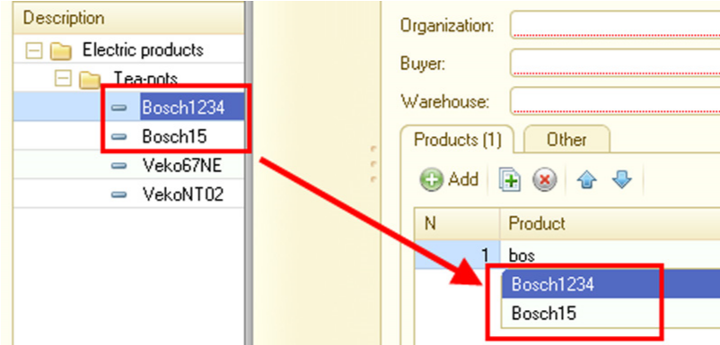
Fig. 116. Input by String
For example, you have a Nomenclature catalog with multiple products that start with Bosch. By entering bos in the nomenclature text box you can obtain a list of goods that start with this word (see fig. 116).
You can use the following attributes to perform searches:
Code and Description for catalogs, charts of characteristic types, charts of accounts, charts of calculation types and exchange plans;
Number for documents;
Number and Description for business processes and tasks;
Attributes of the Number or String type with their Index property set to Index or Index with additional ordering. An example would be the text box for input of article, barcode or TIN.
To generate a list of attributes, press the selection button and in the dialog box that opens move the fields for which input by string is permitted to the left-hand list.

Fig. 117. Setting Up Input by String
For multiple fields, specify the order. When you search for a string, the search will scan the fields in the same order as their order in this dialog box. For example, for a Nomenclature catalog item, you can enter items by Code or by Part #. When the value of an item's code matches the value of another item's Part #, these values will be listed in the order in which they are specified in the settings.
IMPORTANT!
When you search for data (use input by string), data access restrictions are applied (see page 1-188).
5.6.6.1. Input Field Behavior
When entering data into text box, you should know some features of selection lists.
If the entered text allows the system to expressly identify the object wanted by the user, it inserts the object automatically in the text box.
If the text entry results in finding multiple objects that start with the entered text, a drop-down list of these objects is displayed (up to 50 items). When entering the text, you can navigate through the list using the Up Arrow and Down Arrow buttons, while continuing to enter the text in the text box. In this case you can select the item you want and confirm the selection by pressing Enter or Tab.
5.6.6.2. Programmatic Generation of Selection Lists
If a developer is not satisfied with the procedure of selection list generation, it can be overridden.
Two methods are available:
In the form directly: In this case a special procedure of selection list generation is only used in this particular field;
In the module of the relevant object manager: In this case a special procedure of selection list generation is used for all text boxes used to enter values for the object.
If a field is linked to data with an application object reference type (for example, CatalogRef, EnumRef, etc.), you can generate a selection list in the manager window of the corresponding object or by using form module handlers. In other cases you can generate a selection list only by using form module handlers.
For details on the latter method see below.
To generate a selection list programmatically, you have to override the ChoiceDataGetProcessing event handler of the object manager. The handler receives a set of parameters that define conditions of selection list generation.
The set of parameters is a structure containing the following items:
A search string: A string containing the text entered by the user in the text box. This parameter is always used.
Filter: A structure that describes the filter in the same way as the Filter form parameter for extending the form for the dynamic list. This parameter is always used.
A property that indicates the group and item selection mode (it is passed for hierarchical lists only).
In addition, the structure receives items set in the following form element properties: Choice parameter links and Choice parameters.
The handler also receives a variable it uses to return the generated selection list and the StandardProcessing parameter that determines the system behavior after the handler completes its work.
If the developer sets StandardProcessing to False, the complete selection list must be generated by the developer (considering it can contain up to 50 visible items).
If the standard processing flag is set to True, the system can generate the selection list, but you can modify parameters selection (by adding additional filter values, changing the group and item selection mode, etc.).
NOTE 1
If the selection list is generated by the system, it applies the relevant data access restrictions (see page 1-188).
NOTE 2
The examples you can see below are not complete. They only demonstrate various methods of selection list retrieval.
Thus, when a user enters any text, the following code generates a selection list consisting of three goods with 00000002, 00000003 and 00000004 codes.
Example:
Procedure  ChoiceDataGetProcessing(ChoiceDataChoiceData, Parameters, StandardProcessing)

ChoiceDataChoiceData = New ValueList;
ChoiceDataChoiceData.Add(Catalogs.Goods.FindByCode("00000002"));
ChoiceDataChoiceData.Add(Catalogs.Goods.FindByCode("00000003"));
ChoiceDataChoiceData.Add(Catalogs.Goods.FindByCode("00000004"));

StandardProcessing = False;

EndProcedure
In the example below the filter generated by the text box is extended with an additional filter that excludes services from the selection list. The selection list is generated by the system.
Example:
Procedure  ChoiceDataChoiceDataGetProcessing(ChoiceDataChoiceData, Parameters,  StandardProcessing)

Parameters.Filter.Insert("Type",  Enums.ProductTypes.Product);

EndProcedure
The last example is a simplified case of filter implementation by using the 1C:Enterprise script only. This code filters goods with names that start with a user-entered string.
Example:
Procedure  ChoiceDataChoiceDataGetProcessing(ChoiceDataChoiceData, Parameters,  StandardProcessing)

Query = New Query;
Query.Text = "SELECT ALLOWED
|   Goods.Ref as  Product
|FROM
|  Catalog.Goods AS  Goods
|WHERE
|  Goods.Description  LIKE &Description";
Query.SetParameter("Description",  Parameters.SearchString + "%");

Result = Query.Execute();
ResultTable = Result.Unload();
ProductArray = ResultTable.UnloadColumn("Product");

ChoiceData = New ValueList;
ChoiceData.LoadValues(ProductArray);

StandardProcessing = False;

EndProcedure
Please note there is another method of selection list generation: you can pass a structure with special content as a value list item instead of a reference to the object to be found (as in the examples above).
This structure consists of the following items:
Value: A value of the selected item. The structure item with this name is mandatory.
DeletionMark: A flag specifying that the selected value is marked for deletion in the infobase. The structure item with this name is optional.
Warning: A string with the warning text displayed by 1C:Enterprise when an item of this kind is selected from a value list. The structure item with this name is optional.
If the DeletionMark property in the structure is set to True and the Warning property is not set, the system auto-generates the warning text. If the Warning property is set, it is the one to be displayed. Please keep in mind that the Warning text ends with a question Continue? and has two options to select from: Yes and No.
Below you can see a modified code from the previous example where warehouses with the DontUse attribute set to True have the following warning generated:
This warehouse should not be used.
You can also include both Structure type values and ordinary values in a single selection list.
Example:
Procedure  ChoiceData GetProcessing(ChoiceData, Parameters, StandardProcessing)

StandardProcessing = False;
ChoiceData = New ValueList;

//Generate a list with warnings
Query = New Query;
Query.Text = "SELECT
|    Warehouses.Ref,
|  Warehouses.Description,
|   Warehouses.DontUse
|FROM
|  Catalog.Warehouses  AS Warehouses";

Result = Query.Execute();
SelectionDetailRecords = Result.Select();

While SelectionDetailRecords.Next() Do

Structure = New Structure("Value",  SelectionDetailRecords.Ref);

//Enter the warnings
If SelectionDetailRecords.DontUse Then
Structure.Insert("Warning",  "This warehouse should not be used.");
EndIf;

Item = ChoiceData.Add();
Item.Value = Structure;
Item.Presentation = SelectionDetailRecords.Description;

EndDo;

EndProcedure
NOTE
If presentations of items (including structure items named Value) are not expressly specified, they are retrieved automatically.
5.6.7. Forms
Forms are objects created specifically for entering and viewing information and for managing various processes. The program uses forms to ask the user for information it needs to continue processing or to display information the user can view and edit.
If you need to ensure the configuration can work in both the ordinary and managed modes, you can use additional forms of metadata objects. 1C:Enterprise automatically picks the form corresponding to the current operation mode.
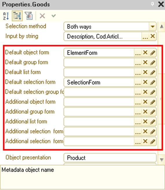
Fig. 118. Main and Additional Forms
Thin clients and web clients only work with managed forms. It means the following:
If both of the assigned forms are managed, the form marked as the main one is displayed;
If only one of the assigned forms is managed, it is displayed; If no managed form is assigned, it is auto-generated.
The thick client picks the form that is the most appropriate for the current run mode.
If no forms are assigned, the following is generated: ○ An ordinary form in the ordinary mode; ○ A managed form in the managed mode.
If only one form is assigned, it is the one to be opened;
If two forms are assigned (an ordinary and a managed form), the following is opened:
○ An ordinary form in the ordinary mode; ○ A managed form in the managed mode.
If two ordinary forms and two managed forms are assigned, the form marked as the main form is opened.
You can use a duplicate set of forms if you switch your configuration from the non-managed to the managed mode or if you want to make configuration functionality partially available at the web client (or the thin client). In this case you can implement the required features in the managed forms and mark them as additional forms. Then the right (managed) forms will be used in the web client (thin client) mode.
However, you should remember that default form retrieval in the thick client is affected by the following configuration properties: Use managed forms in ordinary application and Use ordinary forms in managed application:
If the Use managed forms in ordinary application configuration property is set to False, retrieving a default form in the ordinary mode at the thick client must always result in an ordinary form. If neither the main form nor the additional form is ordinary, an ordinary form is generated. When specified, however, the default constant form (Default Form property) is used regardless of whether Use managed forms in ordinary application is checked or not.
If the Use ordinary forms in managed application configuration property is set to False, retrieving a default form in the managed mode at the thick client must always result in a managed form. If neither the main form nor the additional form is ordinary, a managed form is generated.
If a form opens that is automatically generated by the system and the client application run mode is different from the run mode set in the Default run mode configuration property, the object forms and recordset forms are opened only in Read only mode. Generate commands will not be included in list forms and object forms and Create commands will not be included in list forms, if to run these commands the system needs to automatically generate a form applicable for the current run mode and the client application run mode is different from the mode set in the Default run mode configuration property.
If a managed application is selected as default run mode, a form purpose can be selected for each managed form of the application. The form property Use purposes is equivalent in terms of content and usage to a similar configuration property (see page 1-163). Form editor behavior depends on a cross-section of multiple configuration purposes and the specific form.
If such a cross-section has no value, Personal computer is specified:
The properties of attributes, parameters, commands, and elements that are not supported by a mobile platform are unavailable in the property palette.
Editing the context menu of a form item is unavailable.
Editing an extended tooltip of a form element is unavailable.
Form fields that are not supported by a mobile platform are unavailable (see page 2-919).
The dynamic list settings editor does not support expanding available fields (this is due to the fact that a dynamic list on a mobile platform only works with one table).
If a purpose of the form does not include Mobile application, it is not included in the mobile application configuration.
5.6.8. Commands
You can perform operations with a specific metadata object using this object's commands. Please note that non-parameterized commands of the object are available in the command interfaces of subsystems that include this metadata object. If a command is parameterized, it is available in forms that contain form attributes (including top-level subordinate attributes of the main form attribute) of the same type as the command parameter type.
Commands require command execution procedures. To write these procedures, use the command module for where you need to implement CommandProcessing() handler. This procedure must be preceded by the &AtClient directive because the command is executed in the client application. However, other procedures and functions in the command module can be preceded by other directives if it is required for command execution. For details on compiler directives see page 1-161.
A command module could contain, e.g., a procedure that opens a report form with a preset parameter to print out a specific account card or a procedure that opens a product list form with a predefined filter by product type. If a command belonging to the Navigation panel group should open the same form in different tabs, you should specify a unique key or a unique form parameter to receive (or open) a form.
NOTE
If a command is located in the main application window navigation panel (see page 1-83), re-selection of this command will not lead to its repeated execution. This applies both to standard commands and commands created in the configuration.
5.6.9. Attribute Fill-in Mechanism for New Objects
You can fill in attributes of new objects when you create them interactively (except when they are copied), use the input-on-basis procedure, apply OpenForm()/ GetForm() methods or explicitly call the Fill() method. You can fill in attributes with the following values:
Filter values, when entering values from a list;
Specific values indicated in the attribute properties in the configuration (fill-in values);
Values specified by the developer in the Filling() event handler.
Fill-in processing is implemented for the following objects:
Exchange plans
Catalogs
Documents
Charts of characteristic types
Charts of accounts
Charts of calculation types
Information register record sets
Business processes
Tasks
The Filling() handler uses the FillingData parameter to retrieve the filling data. Depending on how you call the handler, the FillingData parameter can take on different values:
Generation based on another object: A reference to the source object is passed as a parameter value. In this case the FillingData parameter is a reference to the database source object.
Selection from a list with a filter applied: The passed parameter value is a structure that contains filter items with their comparison type set to Equal to or In list (the list has a single value). When a new document is created in the document journal form, items of the journal column filter are preliminarily converted so that the FillingData structure item is named after a document attribute rather than a journal column.
Input of a new object or record without applying a filter: The parameter value is Undefined.
Input of a new object or record using a global command: The parameter value is Undefined.
Execution of OpenForm()/GetForm() methods from 1C:Enterprise script: If OpenForm()/GetForm() methods result in a new object form, a Structure type value of the FillValue form parameter is passed as a parameter value to the FillingData handler. If the FillValue parameter is not specified in the form parameters, the handler parameter value is set to Undefined.
Calling the Fill() object method from 1C:Enteprprise script: The passed parameter value is the information passed as a Fill() method parameter.
NOTE
When a new object is created interactively by copying, this operation is processed in the OnCopy() handler of the corresponding object.
If attributes are filled in from the filling data, this process is affected by the Fill from filling data property of the metadata object attribute. If this property is set to True, the attributes are auto-filled by the system from the filling data. If the property value is False or the filling data do not contain the required value, the system attempts to fill in the attribute using the Fill value property.
IMPORTANT!
A developer can control how both custom and standard object attributes are filled in. For example, the developer can disable auto-filling the Parent standard attribute with the current group.
If the StandardProcessing parameter equals True after the Filling() handler is executed, the system auto-fills the attributes (including the standard attributes) that have their Fill from filling data or Fill value property set in the metadata and are not filled in the handler (their value equals the default value for the attribute type). The Fill from filling data property is automatically set by the system for certain standard attributes of specific objects:
For catalogs – Parent and Owner attributes;
For charts of accounts, charts of characteristic types and charts of calculation types – Parent attribute;
For information registers – leading dimensions;
For standard attributes of other objects this property is not set by default. The system retrieves data for filling standard attributes from data attributes with the same names passed in the FillingData parameter.
The filling data are passed to the created object form as a standard parameter of the FillingValues form and are later passed from this parameter to the object as an extension of the form to be filled. You can also set the FillingValues form parameter of the new object programmatically; in this case all actions characteristic of interactive object creation are performed.
NOTE
If you create a new object programmatically, filling is not automatically called by the system. Instead, you should call the filling handler using the Fill() method.
Fill value: This property of a metadata object attribute can be used to specify a default value the attribute takes on when an object is created interactively.
IMPORTANT!
Attributes can be filled in from the Fill value property after the Filling() handler is called. The attribute is filled if its value has not been filled in previously (by the Filling() handler or the standard filling procedure).
The value types matches the attribute type. Please note that you can specify primitive types or predefined data as values for this property.
5.6.10. Attribute Fill Check
Data in the information system can be entered using multiple methods which are frequently invalid. Therefore, a lot of effort is invested in validating the entered data and notifying the user if the data are invalid at the solution development stage.
The fill checking process facilitates configuration development considerably.
The platform supports auto-check of the specified application object and form attributes and enables module checks.
The platform auto-checks filling for the following objects:
constants
catalogs, documents, reports, data processors, charts of characteristic types, charts of accounts, charts of calculation types, business processes and tasks:
○ attributes and standard attributes
○ tabular sections
○ attributes and standard attributes of tabular sections
record sets of accounting registers, information registers, accumulation registers, calculation registers, recalculations and sequences:
○ dimensions
○ resources
○ attributes and standard attributes
form attributes
report form attributes
data processor form attributes
NOTE
Attribute fill checking is similar to the ValueIsFilled() function. In tabular section fill checking a tabular section is filled if it contains at least one row.
You can call a fill check using one of two methods: Call the FillCheck() method (for an object or a form); Use automatic calls.
IMPORTANT!
If the Compatibility mode is set to Version 8.1, automatic fill checks are unavailable.
5.6.10.1. Default Settings
By default the properties listed below are set to Display error for the following standard attributes:
ExchangePlan – Description
Catalog – Owner, Description
Document – Date
ChartOfCharacteristicTypes – Description
ChartOfAccounts – Code, Description
ChartOfAccounts.ExtDimensionTypes – ExtDimensionType
ChartOfCalculationTypes – Description
ChartOfCalculationTypes.LeadingCalculationTypes – CalculationType ChartOfCalculationTypes.BaseCalculationTypes – CalculationType
ChartOfCalculationTypes.DisplacingCalculationTypes – CalculationType
InformationRegister – Period
AccumulationRegister – Period
AccountingRegister – Period
CalculationRegister – RegistrationPeriod, CalculationType, BegOfAc- tionPeriod, EndOfActionPeriod
BusinessProcess – Date
Task – Description
5.6.10.2. Procedure
Fill auto-check is called by a form extension before all objects, except document, business processes, report and data processors, are written interactively. The following behavior is defined for the following objects:
For documents:
○ Fill check is called by the form extension before posting if the Post property is set to Enable;
○ Fill check is called by the form extension before writing if the Post property is set to Disable;
For business processes fill check is called by the form extensions before the start;
For report fill check is called by the form extension when the Create button is pressed;
For data processors fill check is called by the form extension in cases when buttons related to standard form commands are pressed: OK, Yes, Retry, Ignore.
If an attribute is the main form attribute with one of the following types: CatalogObject, DocumentObject, ReportObject, ChartOfCharacteris- ticTypesObject, ChartOfAccountsObject, ChartOfCalculationTypesObject, BusinessProcessObject, TaskObject, a fill check is also called for its value.
For the system to call the fill check, the form where you work should have its Check fill automatically property set. In this case the system calls the form's FillCheckProcessingAtServer() handler first and then calls the object module's FillCheckProcessing().
IMPORTANT!
If the form's Check fill automatically property is set to True when you execute standard commands, such as Write (Post for documents, etc.) or standard form commands (OK, Yes, Retry, Ignore), the FillCheck() method is called. Otherwise the fill check is called neither for the form nor for the object.
The following procedure is used for fill checking:
A list of form attributes that can be checked for filling and have their FillChecking property set to ShowError is created. This list does not include attributes of the type that does not support fill checks (e.g., CatalogObject); however it includes the main form attribute name.
Form attributes disabled by functional options will not be included in an automatically generated list of attributes.
The form's FillCheckProcessingAtServer event handler is called; a developer can use it to describe a custom fill check algorithm or modify the list of attributes to be checked. The created list of attribute names is passed to the handler. You can only add attributes to the list in the handler if they belong to the types listed above (that support fill checks in forms) or are the main attributes. Adding object-type attributes (e.g., CatalogObject) to the list raises an exception during the subsequent auto-check. Adding a non-existing attribute name to the list raises an exception during the subsequent auto-check.
When the event handler execution is completed, the fill check procedure gets a list of the checked attributes (the list might have been changed by the handler). The system analyzes the list of attributes and checks each attribute for filling. If an attribute is a main object-type attribute (e.g., Object of the CatalogObject type), the fill check is called for the object. If an attribute is an object-type attribute, but is not the main attribute, an exception is raised.
A developer can modify the check process by defining a FillCheckProcessing event handler in an object, record set or form module.
This allows the developer to gain full control over fill checks. The Chec- kedAttributes parameter is used to pass an array of parameters that are selected for the check in the Designer to the handler. The developer can modify this array in any way:
Delete the attributes that undergo custom checks or do not need to be checked now;
Add the required attributes that need to be checked for filling.
If the developer does not want to use the standard check procedure, he or she can use a custom algorithm instead and implement the UserMessage object to notify users of the detected issues.
If the check process displays error messages to the user, the Cancel parameter should be set to True for the platform to know that the current action cannot be completed.
The CheckedAttributes event parameter contains attribute names in the following formats:
For attributes and constants – AttributeName, e.g. Vendor;
For tabular sections – TabularSectionName, e.g. Goods;
For tabular section attributes – TabularSectionName.AttributeName, e.g. Goods.Nomenclature;
For form attributes – AttributeName, e.g. DocumentObject.
If attributes are a part of functional options (see page 1-211) without parameters, option values are accounted for during fill checks. If the functional option is enabled, the attribute is added to the list of checked attributes; otherwise the attribute is not added to the list. It means the disabled field is not passed to FillCheckProcessing in CheckedAttributes parameters.
If attributes are a part of functional options with parameters (see page 1-211), they are always included in the list of checked attributes (CheckedAttributes parameter). In this case if you want to delete an attribute from the checked attributes list, you should use the FillCheckProcessing handler. First, you need to retrieve a value of the functional option by specifying the required object data as parameters.
5.6.10.3. Mark Incomplete Display Rules
The following properties of configuration elements have an impact on mark incomplete display:
Fill ñheck property of a metadata object attribute;
Fill ñheck property of a form attribute;
Automark unfilled property of a form element;
MarkIncomplete property of a form element (it can only be modified programmatically).
The Automark unfilled property of a form element can take on the following values:
Auto: The mark is displayed if the form attribute or the metadata object attribute has its Fill check property set to Display error and the attribute associated with the form element is empty.
Yes: The mark is displayed for an unfilled item regardless of the Fill check property value.
No: The mark is not displayed for an unfilled item regardless of the Fill check property value.
If an incomplete mark is not shown when a text box is interactively changing, MarkIncomplete property values do not change. Marking is shown again (if necessary) after interactive editing in the text box is completed or the value is set. The system can change the MarkIncomplete property if the AutoMarkIncomplete property is set to True:
if the field value is not entered, the MarkIncomplete property is set to True; if the field value is entered, the MarkIncomplete property is set to False.
NOTE
If the MarkIncomplete property is set for a table with no rows, the first row is highlighted; if, however, the table is filled, all rows are highlighted.
Additionally the incomplete mark is displayed if the message window contains a message (see page 1-353) associated with a specific form field, regardless of the specified properties of the form element and the associated attributes. After the message window is cleared, the incomplete mark is removed for all form elements if their MarkIncomplete property set to False.
5.6.11. Indexing Object Attributes
Most configuration application objects have a subordinate Attributes group. This group contains additional characteristics of these objects.
In the 1C:Enterprise mode it is often necessary to filter data based on a certain attribute or to sort data lists based on attributes. 1C:Enterprise can be used for this purpose; however, in case of large data amount this task may take a long time.
To speed it up, you can specify the Index property for the attributes that will be used for filtering or sorting. If this property is set (the Index or Index with additional ordering value is selected), these tasks will be performed faster. For primitive attribute types, attribute indexing makes it possible to sort lists by clicking in a column title.
In addition to sorting by attributes or filtering data by an attribute value, it is often required to sort data by its main presentation (e.g., description or code) in the resulting list, i.e. to sort records by presentation within each attribute value. To get the correct result, select the Index value and specify both the attribute and the presentation in the list sorting criteria.
If you need to minimize filtering or sorting time, choose the Index with additional ordering option for the attribute (if available).
IMPORTANT!
You can effectively use the additional sorting tool only when a certain sorting order is specified in the 1C:Enterprise mode in the list sorting criteria: first by attribute, then by presentation.
If such sorting criteria are not specified, there is no need to specify the Index with additional ordering option, since it will be equivalent to normal indexing, however the index size will be greater.
Indexing with additional ordering is used for attributes of catalogs, documents, charts of characteristic types, charts of accounts and charts of calculation types.
Normal indexing can be used for register attributes.
5.6.12. Rights
You can edit rights of access to configuration objects both in the editor of role access rights (see page 1-185) and in the object editing window (see page 1-59).
You can use the object editing window to set up access rights for a specific object in all roles existing in the system. You are allowed to set access rights:
For metadata objects
For tabular sections
For object attributes
5.6.13. Quick Choice
When text boxes are filled in, the method of object selection is defined by the Choice Method and Quick choice properties.
The Quick choice property manages the default selection mode. This property is only available if the Choice Method property is set to Both ways. Review the example below to see how the Quick choice property works.
Assume you have a Warehouses catalog. Its Choice Method property is set to Both ways; its Quick choice property is also set. In this case values from the Warehouses catalog are selected in the quick selection mode by default throughout the entire configuration. If you disable the Quick choice property, the selection mode changes to Using form by default.
You can also expressly override the selection mode for a metadata object attribute or a form element. To do so, you can just change the Quick choice property value from Auto to Use, thus enabling the quick selection or None, disabling it. By default, the Quick choice property for a metadata object attribute or a form element is set to Auto.
Therefore, the system of selection mode management has three levels:
1. First, the platform analyzes the form element Quick choice property.
2. If set to Auto, the property is checked for the object attribute.
3. If Auto values match, the platform analyzes the Choice Method and Quick choice properties of an application object that corresponds to the attribute type. If the Quick choice property is set to a value other than Auto at the first or the second level (form element and object attribute), the check is terminated and a selection is made in the specified mode.
NOTE
If the Choice Method property of an application object is set to Using form or Quick choice (not Both ways), specifying Quick choice properties for an attribute or a form element has no impact on the selection method.
5.6.14. Choice Parameter Links
The Choice parameters links property is used to create a list of attributes that will provide values to be used when selecting an attribute value, opening a selection form or displaying a quick selection list and using input by string.
As an example, consider selecting a contractor agreement. First, you select a contractor, then you select an agreement from the list of agreements of the selected contractor. If you change the contractor, the list of agreements changes automatically.
To restrict selection, the attribute in the Choice parameters links property is set to the attribute to be used when filtering the selected values and the attribute to be used as the source of the filtering value.

Fig. 119. Choice Parameter Links
Values indicated in this property are passed to the form to be opened through the Parameters structure. Please note that the value in the Name column matches the structure item key, while the attribute value in the Attribute column corresponds to the structure item value. If the Name column contains a value of the Filter. Owner type, a Filter parameter (of the Structure type) is created for the form. The item created in this structure will have the Code key and a value retrieved from the attribute indicated in the Attribute column (Supplier in this example).
If the name of an item in Choice parameters links matches the name of an item in Choice parameters, the item from Choice parameters links will have maximum priority (the item from Choice parameters is ignored), when the value of the field specified in the Choice parameters links item and passed to the ValueIsFilled() function returns True. At that the item from the Choice parameters property is ignored.
You can also use the choice parameter links window to clear the field when link fields are modified. If the Edit mode of the linked value property is set to Clear, the field is cleared when the link value is modified interactively (selecting the value previously specified in the field again is also a modification) before the OnChange event. Otherwise the field is not cleared (the property value is Do not change). Elements are cleared regardless of a real value change in the link element beforethe OnChange event handler is called.
If the field displays table data (a table column or an individual field associated with the current data), it is cleared if the source of data for the form table is FormDataCollection or FormDataStructureAndCollection. If the attribute you want to clear is associated with table data, while the link attribute is not, values in all table rows are cleared.
The attribute cannot be cleared if it is associated with a column of the DynamicList type attribute.
For a standard Parent attribute of a subordinate catalog the Choice parameters links property can be changed by the system automatically. It could happen in the following cases:
When the catalog subordination state changes;
When the Hierarchical property value for the catalog changes.
The following procedure is used:
If the catalog is subordinate and hierarchical, a value with Name = Filter.
Owner and Attribute = Owner is added in the list of Choice parameters links property values for the Parent attribute;
Otherwise the value with Name = Filter.Owner and Attribute = Owner is removed from the list of Choice parameters links property values for the standard Parent attribute.
Review the following example: a form contains Vendor and VendorAccount fields. The ChoiceParameterLinks property for the VendorAccount field is set to Object.Vendor that is displayed in the Owner filter field.

Fig. 120. Clearing Associated Form Elements
Then, if you change the Vendor field value interactively, the VendorAccount field value is auto-cleared.
5.6.15. Choice Parameters
The Choice parameters property can be used to specify parameter values to be applied when selecting an attribute value. This restriction applies when you open a choice form, display a quick selection list or use input by string. For example, you might want to restrict the selection to the products with the Type attribute set to Enum.ProductTypes.Service. You can specify a list of values for a specific filter value. To do so, select the FixedArray type when you edit the Value column.

Fig. 121. Parameters selection
Values indicated in this property are passed to the form to be opened through the Parameters structure. Please note that the value in the Name column matches the structure item key, while the value in the Value column corresponds to the structure item value. If the Name column contains a value of the Filter.Code type, a Filter parameter (of the Structure type) is created for the form. The item created in this structure will have the Code key and the Value value.
If the name of an item in the Choice parameters links property matches the name of an item in the Choice parameters property, the item from Choice parameters links will have maximum priority (the item from Choice parameters is ignored). The item priority is maximum when the value of the field specified in the Attribute parameter of the Choice parameters links item is filled (the ValueIsFilled() function returns True for this value).
NOTE
Values specified in the Choice Parameters attribute property are also used by dynamic lists and the data composition system.
If you select extra dimension values in a table cell linked to an accounting register recordset, the selection parameter is automatically set for the Owner field, but only if this type of extra dimension has an additional catalog type of extra dimension values. The corresponding extra dimension type is the selection parameter value.
5.6.16. Other
The Use standard commands property defines whether standard commands of a particular object (e.g., commands that open a catalog list) can be added to the command interface. If this property is set to False, the standard commands are not displayed in the system and you can only include the object in the interface by using a command created in the Designer.
The Choice form property determines a form to be used when selecting an attribute value. It is used for attributes with the types based on metadata objects that use forms. For example, a Goods catalog might have multiple selection forms, but the standard Parent attribute requires a special form. If you want to implement this behavior, specify this form in the Choice form property for the standard Parent attribute (for details on standard attributes see page 1-253).
Format is used for Number, Boolean and Date types and defines a format to be used when attribute data are displayed.
The Editing format property sets a format to be used when editing data of Number, Boolean and Date types.
Link by type establishes a relational link with the attribute determining the types of values entered in the text box. It is useful to set up type links for attributes that have a composite data type and are logically linked to another attribute, such as ChartOfChartOfCharacteristicTypes.Ref, possibly creating a link between an attribute that contains an extra dimension with an attribute that contains a value of the ChartOfAccountsRef type. An item of the type link contains the number of extra dimension type in case the attribute selected for the type link has a value of the ChartOfAccountsRef type.
For example, you might have two attributes – CharacteristicType and Characteristic. The CharacteristicType attribute's type is ChartOfChar- tOfCharacteristicTypesProductCharacteristicTypes.Ref, while the Characteristic attribute's type is Characteristic.ProductCharacteristicTypes. You can set the Characteristic attribute's property Link by type to CharacteristicType. In this case the selected value type is defined by the type specified for the selected value of the chart of characteristic types.
5.7. CONSTANTS
In 1C:Enterprise, constants are used to store permanent or nearly permanent information. This information either does not change at all or changes quite infrequently. For example, the names of companies usually do not change.
The main reason for using constants is that once information is put there, it can be used for preparing documents, in calculations or in reports. Constant values may be edited when necessary.
Let us look at an example. Company documents are usually signed by the director and the chief accountant. Of course, the officials themselves must sign the documents. However, aside from the signature, it is necessary to provide the signature drill down – last name of the person who has signed the document. Of course, it is possible to enter the names of the director and chief accountant directly in the document forms. However, if one of the last names changes, you will have to edit all of document forms and correct the last names all over again. So it is much easier to create two constants for the last names of the director and the chief accountant and use these constants in the document forms instead of their values. If there is a new director or chief accountant, you only have to change the constants by entering new names and the changes will be automatically implemented everywhere these constants are used.
IMPORTANT!
When value of a constant changes, the previous value is lost. To get the previous data values, you have to use an information register with no dimensions instead of constants.
The 1C:Enterprise Designer can be used to create any number of constants for storing any information.
5.7.1. Properties of a Constant
Use the Constants branch of the configuration tree to work with constants.
Constant properties should be edited in the properties palette. Please note that a constant is a typed configuration object.
Type specifies the type of constant. A constant may be of any standard configuration type (Date, Number, CatalogRef, DocumentRef, etc.) or a composite type (comprising several types).
Depending on the type selected, the properties palette may contain additional properties that refine the selected type.
If you want the constant editing form displayed in the command interface, set the Include in the command interface property. It displays the command that opens the constant editor in the subsystems where the constant belongs. The constant editing form is set up using the Default Form property (for details see page 2-989).
Use the Common forms branch to create constant input forms (see page 1-229).
5.8. CATALOGS
Sometimes, when document forms are filled out, it is necessary to enter information by selecting a value from a preset list.
Let us take an application form to be completed when applying for a job as an example.
When filling out the Place of birth field, it is necessary to specify a city or town. Although the total number of cities and towns is quite big, it is finite. Actually, it is possible to specify a place of birth by selecting a city or town from a list. This list is called a catalog.
A catalog is a list of possible values for a certain attribute of a document (in its broadest sense).
Catalogs are used when it is necessary to ensure consistent information input.
For example, it is necessary to use the same name for an item so that different employees (salespersons, managers and warehouse staff) understand what the item is. In this case a catalog is also needed. Usually in mercantile business such a catalog is stored as a price list. If such a catalog is stored in electronic form, it contains all of the possible items that a business works with.
1C:Enterprise makes it possible to maintain any number of catalogs. Each catalog represents a list of consistent object instances: employees, organizations, goods, etc. We will refer to each object item as a catalog item.
Please keep in mind that the configuration is only used to create the structure of a catalog, while its contents, i.e. catalog items, have to be entered by the user. In the configuration process, it is necessary to describe the structure of the information that will be stored in the catalog, develop the screen and/or print representation of the catalog and specify various characteristics of its behavior.
Catalogs usually have predefined code and description attributes. The code number may be of a Number or a String type.
The 1C:Enterprise system provides you with a wide range of options for working with catalog item codes: the codes are automatically assigned and checked for uniqueness, etc.
A catalog in 1C:Enterprise may have a hierarchical structure. There are two types of hierarchies – the folder and item hierarchy and the item hierarchy. In the first case, all data in the catalog are divided into two types: catalog items and catalog folders. Folders are logical blocks of catalog items. For example, a catalog of goods, where the folders are types of products (Plumbing Systems, Household Chemicals, etc.) and the items are specific products (Mixer, Mirror, Detergent), is a hierarchical catalog.
Using hierarchical catalogs makes it possible to enter information with the required level of detail. Items and folders in a hierarchical catalog can be moved from one group to another.
There are no folders in catalogs with the Item hierarchy. In this case some items may also act as folders. In such catalogs, all of the items have the same functionality. A list of company departments is an example of such a catalog. Each department may be described by the same set of attributes; however, it may logically contain another department or be a component of another department.
For hierarchical catalogs, the Designer makes it possible to specify a limit on the number of catalog levels or to use an unlimited number of nested levels.
In addition to code and description, you can create a set of attributes to store additional information about items in the catalog.
For example, the Contractors catalog may contain information such as the full description of a contractor, tax ID number, the last name of the director and the chief accountant and other information.
If an object of the application domain corresponding to the catalog has both simple properties like a full description or tax ID and composite (list) properties, you can create a set of tabular sections for the catalog.
For example, you can create a tabular section for the list of contractor's telephone numbers in the Contractors catalog.
The names of catalog attributes should not match the names of attributes in a tabular section.
To work with information stored in a catalog, you can create on-screen forms. You can create separate forms for viewing, editing and selecting items from a catalog.
The Designer allows you to create multiple forms of the same type, e.g., forms for selecting an item from the catalog and use them in different situations.
We recommend creating separate forms to display the list of items and to select catalog items.
5.8.1. Catalog Properties
Use the Catalogs branch of the configuration tree to work with catalogs.
When you create a new catalog, the object editing window opens (see page 1-59).
Hierarchical ñatalog – if this check box is selected, the catalog has a hierarchical structure and the Hierarchy type and Number of hierarchy levels can be set.
Hierarchy type specifies which type of hierarchy is used in a catalog. If the Folder and item hierarchy option is selected, the catalog may contain two types of items: folders and items. Folders are used only to hold other folders and items of a catalog. To define a folder, you usually need a code, description and parent (link to a higher level). A catalog item may also contain other attributes specified on the Data tab. For catalogs with this hierarchy type, you can create folder forms and item forms. When Item hierarchy is selected, all items of a catalog are at the same level. Catalogs of departments or cost items may serve as an example.
Folders on top – this property becomes available when Folder and item hierarchy is selected. If the Folders on top property is set and the catalog is displayed as a hierarchical list, its folders are placed on top, above all items. If this property is not set, the folders and items will be arranged according to the specified sorting rules (by code, description, etc.). For example, if a new folder has a code greater than the codes of all other folders and items (when sorted by code), in the former case this folder will be placed below all other folders, but above all other items; in the latter case it will be placed below all folders and items.
Please note that the Folders on top property does not affect how the catalog is displayed as a non-hierarchical list.
Number of hierarchy levels becomes available if the Limit the number of hierarchy levels check box is selected. Catalogs in 1C:Enterprise can have more than one nested level. If the Limit the number of hierarchy levels property is not set, the catalog may contain an unlimited number of nested levels.
Owners: This property has to be explained in detail.
Any catalog may be used independently or as a subordinate to another catalog. For example, a catalog of contracts may be used independently or may be linked with a catalog of companies.
To make a catalog subordinate to any existing catalog, click the editing button in the List of catalog owners field and specify the catalogs that own this catalog in the object selection window. In 1C:Enterprise, the owning catalog is called the owner and the owned catalog is called the subordinate.
Unlike multi-level catalogs, where all items have the same structure, the mechanism of subordinate catalogs makes it possible to connect items with different structures. In this case each item of the subordinate catalog will be logically linked to one of the items of the owner catalog.
For catalogs with several owners, different items may have different types of owners, but one item can have only one owner.
Subordination type allows you to manage owner restrictions. This property specifies whether the owner can use only items, only folders or both. If a catalog has several owners, the restriction applies to all of them.
Code length: This property specifies the maximum length of code for catalog items.
You can specify zero code length in the Designer if a catalog item code is not used.
When this property is specified, it is desirable to determine the code length that is actually possible. Please keep in mind that you can increase code length when needed as you operate the configuration.
NOTE
The maximum code length is 50.
Description length specifies the maximum length of a description for catalog items.
You can specify zero description length in the Designer. It means the catalog has no description.
NOTE
The maximum description length is 150.
The Code series property is used to specify the range for checking code uniqueness and for automated code assignment.
If this property is set to In the entire catalog and you automatically assign or manually enter a code, its uniqueness is checked against all items of the catalog.
The Within subordination area setting works for hierarchical or subordinate catalogs only. In this case the system checks code uniqueness only within folders and items of the owner catalog where a new catalog item is added or where an existing item is edited.
When the code series is set to Within Subordination area, catalog items in different folders may have the same codes. Please keep it in mind when moving items of a multi-level catalog from one folder to another. If the code of an item that is moved is the same as the code of an existing folder item, a warning message is displayed and the item is not moved.
When the code series is set to Within owner subordination area in hierarchical subordinate catalogs, all codes with the same owner and different parents are autonumbered and checked for uniqueness.
The Code type property is used to select a value type for the catalog item code – Number or String. String type codes are useful for complex coding systems in which the code may contain numbers, letters and separators. Articles of clothing may serve as a typical example of a String code.
Please note that String type codes can also be assigned automatically.
For the first item, the system creates a code that looks like 001 (the number of zeros depends on the specified code length), i.e., the code is a string of characters where all characters are numerical. When other items are added to a catalog, the system will keep assigning item codes: 002, 003, etc.
If catalog maintenance requires using mixed alphanumerical codes, codes like AA001 can also be used for auto-numbering. The first component of the code here (AA) is a text prefix, while the second component (001) is interpreted as a number and used for auto-numbering.
For example, if the first code is AA001, the second code will be AA002, the third code will be AA003 and so on.
A text prefix may be set manually (you can use a composite code when adding a new item to the catalog) or using the 1C:Enterprise script (SetNewCode() method).
Allowed code length is available if the Code type property is set to String. You can use this property to adjust the length of the string to store the code. If the property value is Fixed, the length of the string storing a catalog item code always equals the value specified in the Code length property. Otherwise the string length equals the actual number of characters in the item code.
Attributes. A new catalog can be viewed as a table with two columns: the catalog item code and its description. 1C:Enterprise can store additional information about catalog items, other than the description and code. When you edit a catalog, you can specify a set of additional attributes for storing such additional information.
When a catalog is displayed on the screen, these attributes may be displayed as columns in the table box of the catalog's list form. In addition, the information stored in attributes may be used in different calculations, reports, etc.
For example, it is easy to use catalog attributes to organize an employee table. To do this, you need to create attributes that would store information about education, personal data and other HR data in the Employees catalog. Simple built-in search tools make it easy to find the required information about an employee in the catalog when using the configuration.
Tabular sections. Tabular sections are used to describe information that is related to the catalog, but is not used independently. For example, a tabular section may contain information about an employee's family (information about each family member will be described in attributes of the tabular section and there can be any number of family members), the employee's job record, etc.
In the example above, if it were possible to use information about employees' families independently, you could put this information in a separate catalog which would be subordinate to the Employees catalog.
The main difference between a tabular section and a subordinate catalog is that it is possible to reference items of a catalog, unlike lines of a tabular section. When a catalog is accessed, it is loaded into memory together with all tabular sections. If a tabular section has many lines, this may decrease system performance. Therefore, it is recommended that tabular sections be used when there is no need to store item references and when the count of items is limited. Each catalog may contain an unlimited number of tabular sections.
Autonumbering. If this property is set, a code will be automatically assigned to each new item in the catalog. Auto-assigned codes can be modified.
Check uniqueness. If code is used to identify a specific item in a catalog, this code should be unique (have no duplicates). If the Check uniqueness property is set, the code will be automatically checked for uniqueness each time a new item is added to the catalog.
Default presentation specifies how catalog items are displayed. For example, values of the CatalogRef type in a document or catalog attribute or a constant, will be displayed as the code or description of a catalog item depending on the property value. For list forms, this column becomes the default column. When a list is opened, this column becomes active.
Generation. The Generation tab specifies which configuration objects may serve as a basis for objects of a given type and for which objects the objects of a given type may serve as a basis. The Generation settings wizard button launches the "Create Based On" wizard. For more details on working with the wizard, see page 2-985.
An example of document generation is entering a Warehouse Transfer document based on an item of the Goods catalog.
5.8.2. Properties of Catalog Attributes
In addition to the main properties, catalog attributes can also have the following properties:
Type specifies the attribute data type.
Use specifies the attribute's use for folders and items in hierarchical catalogs.
5.8.3. Predefined Catalog Items
A configuration developer can create a set of predefined items and folders (for hierarchical catalogs) for any catalog. These items cannot be deleted in the 1C:Enterprise mode.
You can open the form for entering preset items by clicking the Predefined button on the Other tab in the configuration object editing window. You can only enter main properties of an item (name, code and description) in the Designer. The item name may be used in expressions of the 1C:Enterprise script. The values of other attributes of a predefined item are entered in the 1C:Enterprise mode.
In the 1C:Enterprise mode icons for predefined catalog items and custom items look different.
IMPORTANT!
You cannot create predefined items for a catalog that has an owner, and you cannot set an owner for a catalog that has predefined items.
5.9. DOCUMENTS
A document is one of the main concepts in 1C:Enterprise. Documents are used to enter information about business transactions into the system.
Most documents that are created during task configuration are electronic counterparts of standard paper documents; however, in addition to recording business transactions, this data type may be used to save other data, too.
Every document contains information about a specific business transaction and is characterized by a number, date and time. Date and time are the most important document characteristics, since they make it possible to determine the sequence of operations.
The configuration only describes the document structure; specific document instances have to entered by a user working with the program. For example, the Invoice document in 1C:Enterprise may be used to prepare invoices with different contents and the same attribute sets, the same logic of behavior, etc.
Hereinafter, document structure is referred to as a document, i.e. tools for document input and visualization.
The Designer can be used to describe a document structure, arrange forms for entering information in a document and describe the algorithm of print form creation for the document.
In addition to the date, time and document number, you can create a set of attributes for storing additional information.
If an object of the application domain corresponding to the document has both simple properties like date, number and total amount and composite (list) properties, you can create a set of tabular sections for this document.
For example, you can create a tabular section for a list of items in the Goods Issue document.
A configuration may contain any required count of lists of documents with the same type and document journals with different types. List forms do not have the Document type column (since lists contain documents of the same type), while journals usually do contain this column.
When a document is created, you can specify a list of journals that will be used for working with this document. You can specify one journal for different document types which will allow you to group documents in the journals as needed. You can change the journals assigned to a document.
Documents can change the status of accounting registers (when they are posted). If a document has been posted, the data specified by the user when entering the document affect the system accounting registers, i.e. modify inventory balances, amounts due to contractors, etc. You can post documents in real time (real-time posting) or backdated (regular posting).
5.9.1. Document Properties
The Documents branch of the configuration tree is used for working with documents. This branch also contains service configuration objects – numerators and sequences.
This section describes specific document properties. Common properties of all configuration objects, including documents, are described on page 1-250.
Document properties can be edited using the properties palette or the editing window (see page 1-59). You can configure various document properties at different tabs.
The Main tab contains the main document information.
The Data tab contains attributes and tabular sections.
In the properties palette, the type is specified for each attribute, in addition to the main properties. To enable fast searching or information selection by document attributes, it is necessary to set the Index property for the appropriate attributes (for details see page 1-273).
The Numbering tab contains data that are used to assign document numbering rules.
Each document has mandatory attributes that are created automatically and cannot be deleted. These attributes include the date, time and document number. Unlike date and time, you can specify several parameters for the document number. These parameters will control how this attribute behaves when you work with a document of this type. The combination of these parameters will define the document numbering rules for 1C:Enterprise.
Autonumbering. If you turn this property on, each new document will be numbered automatically. An automatically assigned number can be corrected.
Numerator. A document can be assigned one of the numerators already existing in the configuration. To assign an existing numerator to the document, select the numerator name in the Numerator property. In this case all items on the Numbering tab, except Autonumbering, become unavailable, i.e., the numbering rules for this type of document will be completely defined by the assigned numerator. For information about numerator creation and properties see page 1-290.
Numerators help organize continuous numbering for different types of documents. To do this, you have to assign the same numerator to all documents that should be numbered continuously. Uniqueness check and sequential number assignment will take into account all documents with this numerator.
Number length specifies the maximum length of a document number.
Number format is the same as Code type in a catalog (see page 1-280).
Allowed number length is available if the Number format property is set to String. You can use this property to adjust the length of the string to store the number. If the property value is Fixed, the length of the string storing a document number always equals the value specified in the Number length property. Otherwise the string length equals the actual number of characters in the document number.
If the Check uniqueness property is set, the number of each new document is checked for uniqueness, subject to the restrictions specified by Periodicity.
Periodicity specifies the document number uniqueness check and the number repetition period. If the Check uniqueness property is turned on for document numbers, Periodicity specifies the limits for checking.
If Autonumbering is turned on, 1C:Enterprise will assign a new sequence number to each new document. When the period specified in Periodicity expires, document numbering restarts from 1.
The Posting tab is used to set up behavior during document posting and posting cancellation.
Posting specifies whether the document can be posted when it is saved. If this property is set to Enable, the document modifies the register records (changes their state). This selection also automatically calls the Posting event handler for document posting in the 1C:Enterprise mode which opens when a button with the predefined Save and close action (usually an OK button) is clicked. You can use the register record wizard (see page 2-980) to create the Posting event handler. Open the wizard by clicking the appropriate button at the Posting tab in the Document object editing window.
Real-time posting specifies whether real-time posting is enabled for a document. When a non-current date is selected, documents with enabled real-time posting are posted in regular mode, because in this case an accomplished fact that does not require real-time verification (e.g., checking the balance in the product's invoice) is being recorded.
If Real-time posting is turned on for a document, then zero time is set for a new document. Upon posting, the system receives a real-time timestamp which may be the same as or greater than the current date and time and assigns this time stamp to the document. After that, the document is posted in real time. For details on real-time timestamp see page 1-292.
If a document being edited has Real-time posting turned on, the time differs from the current time and when the document is posted (if the current date is specified), the system asks what type of posting should be used. If you select Real-time posting, then the system sets the current time for the document. If you change the time when the document is edited (e.g., if you specify future time of the current day), the system also sets the current time for the document. If you select Regular posting, then the system sets the time to the beginning of the day if the date format does not require entering the time.
Register records deletion is available if the Posting property is set to Enable. This option defines how all records saved during document posting are deleted when the document is reposted or unposted:
Delete automatically means the system deletes the records when a previously posted document is reposted (prior to writing new records) or when document posting is canceled.
Do not delete automatically means register records are deleted programmatically in special cases. Use this mode to manage deletion during both posting and unposting.
Delete automatically on clearing posting means the system automatically deletes register records only when posting is canceled. Reposting will not result in automatic record deletion. This mode is used by default.
If the Register records deletion property is set to Do not delete automatically or Delete automatically on clearing posting, you should clear any Register Records collection recordsets before the posting operation to avoid information duplication.
Add register records on posting defines how the system behaves when register records are created during document posting:
Record selected (default mode) means a record set of the register record collection is only written if the Write property of the set is True (regardless of whether the records in the set have been modified or not).
Record modified (this mode is set when migrating from 1C:Enterprise 8.1 and older versions) means that the system write the record sets that have been modified (their Write property is automatically set to True).
After the document is written, the system resets the Write property for all record sets that register document records, even if the write operation failed.
Sequence filling sets the automated sequence filling mode. The Sequences tab of the Edit window specifies whether the document is part of a sequence.
At the Journals tab in the document editing window, you can mark document journals that will display documents of this type for 1C:Enterprise users. You can create the required document journal forms later.
The Generation tab contains two lists of configuration objects. The top list should contain objects that may serve as a basis for the document and the bottom list should contain objects for which this document may serve as a basis.
IMPORTANT!
A document may be entered on basis of another document or based on objects of a different type (items of catalogs, charts of characteristic types, charts of accounts or charts of calculation types). A document may also serve as a basis both for other documents and for objects of a different type.
If you want to create a procedure for preparing the created object data based on a sample, use a special wizard. For a description of this wizard see page 2-985.
The Rights box allows you to set the privileged mode for posting (Privileged mode for posting property) and/or for unposting documents (Privileged mode for unposting property):
If this property is set, the system will always post or unpost document in the privileged mode (at the server side and in file mode version). However, the privileged mode is not set if a document is posted or unposted in the client/ server mode at the thick client side. The privileged mode enables you to do the following:
○ Autodelete register records;
○ Autowrite register records;
○ Use an appropriate handler (Posting or UndoPosting). However, objects are written in the regular (non-privileged) mode.
The privileged mode is enabled by the system after the object is written, but before posting starts (before register records are deleted if it is done automatically). The same procedure is used when unposting.
When new documents are created, these properties are set to True if the managed application mode is selected as the main run mode in the configuration properties; otherwise if the ordinary application mode is selected, the properties are set to False.
5.9.2. Document Posting Mechanism
Information about business transactions of a company is stored in registers (see page 1-316). Documents can change the register status. This process is known as posting. It is recommended to use this process to change the register status. Posting can be real-time or regular (Real-time posting property).
NOTE
Generally, real-time posting is used for real-time accounting purposes.
5.9.2.1. Real-Time and Regular Posting
Real-time posting is designed to better separate cases of document posting in real time and document posting that reflects an accomplished fact.
Real-time posting is required when document entry and posting do not just register an event, but are a part of the event and help the operator enter information correctly. Naturally, it only makes sense if the event happens in real time.
A classical example is entering and posting a document that reflects goods sales from a warehouse. When entering this document, the operator has to both enter a valid list of goods purchased by a customer and run various checks. The first check is whether the requested product is available at the warehouse. It is important to remember that the check must also be run for other operators that work concurrently and can order the same products. Accordingly, the system is to prevent operators from selling the same product to two different customers. Additionally you might want to check the amount of credit available to a customer, the payment against the invoice and other aspects.
At the same time, if a document is backdated, i.e. entered when the business transaction has already occurred (e.g., a specific product has been shipped to the customer), there is no need to run checks; all you need to do is to record the event in the accounting register. In this case posting a document only registers the event, without being its part.
Therefore, real-time posting aims to separate two posting options: on the one hand, the user needs to understand which posting option is selected; on the other, the posting algorithm needs to perform actions that correspond to the current posting option.
The posting option (real-time or regular) for a document is selected on the basis of its date. If the posted document date matches the current date, the system posts the document in real time without additional queries. The option is defined by the posting data processor which determines the specific algorithm of document posting.
5.9.2.2. Form Extension and Posting
In addition to the Real-time posting property of a document, you can also set a posting mode for a document form extension. The Use posting mode property can be assigned one of the following values:
Non-real-time. Documents are always posted in the regular mode. If regular posting rights are missing, an exception is raised.
Real-time. Documents are always posted in real time. If regular posting rights are missing and you attempt to post a document that belongs to a prior period, an exception is raised.
Query. The system always prompts the user to select the current posting mode.
Auto. The system uses the following algorithm:
○ If the document date precedes the current date, regular posting is used;
○ If the document date matches the current date, real-time posting is used;
○ If the document date follows the current date, an exception is raised;
○ If the document cannot be posted in the selected mode (insufficient access rights, etc.), an exception is raised;
○ If the posting mode at the client side is unknown, the PostingMode parameter of the BeforeWrite event handler receives the Undefined value.
In real-time document posting, one of the targets is listing documents chronologically on the time scale. This is required, in particular, to write off balances correctly in the balance registers (see page 1-325) of real-time accounting. Document arrangement uses the following concepts: point in time and real-time timestamp. Let us review these concepts in more detail.
A document's position on a time axis is defined with the help of the Date attribute that contains time with accuracy of up to one second. It means you can manage the sequencing of document records. However, where the number of documents being created is large, there will probably be instances in which several documents will have identical dates (i.e. they will be created in the same second). How do we then determine the sequence of document creation?
5.9.2.3. Point in Time
The point in time concept was introduced to deal with just this problem. A point in time is a combination of date, time and a reference to a database object. It allows you to explicitly identify any reference-type database object, but it generally only applies to documents. The point in time also identifies non-object data such as register records that are subordinate to a recorder.
The point in time concept is implemented in the 1C:Enterprise script using the universal PointInTime object.
If multiple documents have identical dates and times, their sequence on the time axis is established based on the references. This sequence may differ from the sequence of document creation and cannot be changed by the user. i.e. the user cannot change the sequence of documents within a second or figure out which document is created earlier or later.
5.9.2.4. Real-Time Timestamp
A real-time timestamp is a value of the Date type. A real-time timestamp is the basis that allows you to actually post documents in real time. The system generates a real-time timestamp for each instance of real-time document posting. Its value is generated based on the current session date and the last real-time timestamp generated.
5.9.2.5. Time Zones
If the system works with multiple time zones, this should be accounted for when retrieving a real-time timestamp. For example, an infobase can be physically located in a single city (time zone), but can be used to record transactions in multiple remote offices (e.g., branches of a holding company) located in other cities (and time zones). In this case you would need each branch to have its own timestamp.
Time zones are accounted for through infobase time zones and session time zones.
An infobase time zone defines the time zone used for a new session by default. When you create an infobase, the infobase time zone is undefined. However, you can specify it using the global context SetInfoBaseTimeZone() method. Information about the infobase time zone is saved in the database and does not modify when the infobase is restored or dumped. Creating an initial infobase image (using distributed infobase mechanisms; see page 2-772) copies the infobase time zone from the original infobase to the image.
If the infobase time zone is not specified, the system uses the time zone of the machine where 1C:Enterprise server is installed (in the client/server mode) or the time zone of the local computer (in the file mode version).
A session time zone describes the time zone for a particular session. By default the session time zone matches the infobase time zone.
You can specify the session time zone using the global context SetSessionTi- meZone() method. The session time zone is saved until the session ends. It is used to define the current date of the session and to retrieve a real-time timestamp.
5.9.2.6. Retrieval of Real-Time Timestamp
In real-time posting, the system modifies document time so that the next document posted in real time has a later point in time compared to the previously posted document. It is implemented through real-time timestamps. Real-time timestamps are retrieved by the system automatically during real-time posting; however, they can also be explicitly obtained in the 1C:Enterprise script using the GetRealTimeTimestamp() method based on the current session date.
The current session date is the system date recalculated to match the session time zone. It means the local computer time is recalculated into the zone time defined by the session time zone. This recalculation uses Universal Time Coordinated (UTC).
All users call a single real-time timestamp mechanism that provides each user with the next timestamp in turn. The mechanism of real-time timestamp retrieval returns date that is greater than the previous timestamp received by this or another user in the current time zone. Generally, the system returns the current session time as the real-time timestamp. However, if the current time is greater than or equal to the last timestamp returned to any user, the returned value is one second more than the last timestamp value. Thus, it ensures that each call returns a value that matches the current time, whenever possible and is always greater than the last returned value.
Please keep in mind that different session with the same time zone use the same time to obtain real-time timestamps. Therefore, the number of unrelated real-time timestamps is defined by the number of unique time zones set as session time zones.
5.9.3. Numerators
A numerator is a configuration object that defines document numbering rules: document number type and length, periodicity, requirements for uniqueness check.
The main purpose of the numerator is to provide continuous numbering for documents of different kinds. For this purpose, the same numerator is assigned to such documents.
5.9.3.1. Management of Numerator Lists
To work with Document numerator configuration objects, you have to use the configuration branch within the Documents branch that starts from the Document numerators keyword.
5.9.3.2. Numerator Properties
This section describes numerator-specific properties. Common properties of all configuration objects, including numerators, are described on page 1-250.

Fig. 122. Numerator Properties
Number Type. Type of document number value: numeric or text. Text numbers are useful for complex document numbering systems. The document number may contain numbers, letters and separators.
Number Length specifies the maximum length of a document number.
Periodicity specifies the two important characteristics of the numerator: document number uniqueness check and the number repetition period.
If the Check Uniqueness property is turned on, Periodicity specifies the range for checking.
For example, if Within a day is set as the periodicity option, document number uniqueness will be controlled within a 24-hour period: on the next day, the document numbers may repeat; however within the same day they will be unique.
If Autonumbering is turned on (see page 1-286), 1C:Enterprise will assign a new sequence number to each new document. When the period specified in Periodicity expires, document numbering restarts from 1.
If the Check Uniqueness property is set, the number of each new document is checked for uniqueness, subject to the restrictions specified by Periodicity.
5.9.4. Document Sequences
Document sequences are auxiliary configuration objects. They are intended for timely posting of specific documents.
All documents in the 1C:Enterprise form a single time sequence. To make this possible, every document has its own date and time. If two documents have the same date and time, they are still placed in a certain sequence which depends on the time they were entered into the system. You can change a document's date and time. Therefore, regardless of the entry order, the documents may be placed in any sequence corresponding to the actual sequence of the business events represented by these documents.
When a document is posted in 1C:Enterprise, the system performs certain actions that are recorded by the document in multiple accounting mechanisms supported by 1C:Enterprise.
The document posting algorithm usually records information saved in a document (in its attributes and tabular sections). However, in some cases, the document posting algorithm also analyzes current totals and uses them in posting. For example, if a document is used to write off goods or materials at average cost, the algorithm determines the write-off amount by analyzing the inventory balances of goods (or materials) at the document time. If goods or materials are written off using LIFO or FIFO methods, the posting algorithm will analyze the remaining inventory balance of goods (or materials) by lots for date and time of document posting.
It is obvious that posting of documents based on total results should follow a strict sequence. However, it often becomes necessary to input or correct some documents post factum, due to human errors or document delays. In this case posting of register records generated by subsequent documents (created after the corrected document) will be considered incorrect. For example, if it turns out that a receipt that was entered at the beginning of the month contained the wrong amount of goods, it is necessary to reanalyze all subsequent invoices that write off available lots and to re-write the register records. In other words, all documents that analyze the remaining inventory and come after the changed document have to be reposted.
Sequences branch objects are used for automatic check of document reposting. Each Sequence object in the configuration checks posting of documents of the specified types. Therefore, there may be multiple independent sequences in the system.
5.9.4.1. Management of Sequence Lists
Sequence configuration objects are created in the Configuration window. Each sequence uses a separate configuration tree branch that is located within the Documents branch and starts from the Sequences keyword.
5.9.4.2. Document Sequence Properties
This section describes properties specific to document sequences. Common properties of all configuration objects, including document sequences, are described on page 1-250.
Sequence properties can be edited in the Sequence editing window.
You can select documents in the sequence and register records that influence the sequence at the Usage tab (see fig. 123).

Fig. 123. Sequence Properties
Move the boundary when posting. If the Move option is enabled, when you post a document registered in this sequence, it will try to move the boundary of the sequenced documents. If the property value is Do not move, the posted document will not move the boundary of this sequence.
Incoming documents. The top list of the Sequence window contains document types for a specific sequence.
Select documents types that analyze values of different registers during posting as documents affected by this sequence. Such documents may include invoices, transfer orders, sales orders, etc.
Register records that affect the sequence is one of the main sequence properties. It defines register records that will influence re-posting of documents in the sequence, i.e. accounting mechanisms that will be used for posting of documents in the sequence. For example, such records may include register records.
To configure this parameter, add register types that influence the current sequence to the list.
Dimensions. Sequences may have subordinate objects known as dimensions which are created on the Data tab of the Edit window.
If no dimensions exist for a sequence, then all incoming documents will be reposted when this sequence is restored. If you want the sequence to cover specific rather than all situations, add a dimension to the sequence. In this case re-posting will be needed only for documents that change the register value allowing for the dimensions properties.
If sequence register values change, all later documents with the same attribute values (listed in the Document Attributes Mapping dimension property) included in the attributes of the deleted (added) register records (listed in the Register records attributes mapping dimension property) become invalid.
For example, a sequence takes into account register changes for Goods Receipt and Goods Issue documents. If additional criteria need to be taken into account for reposting of specific documents (e.g., it is necessary to repost documents related to a specific item), then a dimension has to be added to the sequence. Use the dimension's properties palette to specify the dimensions type (Cata- logRef.Nomenclature) and to link it to register attributes.
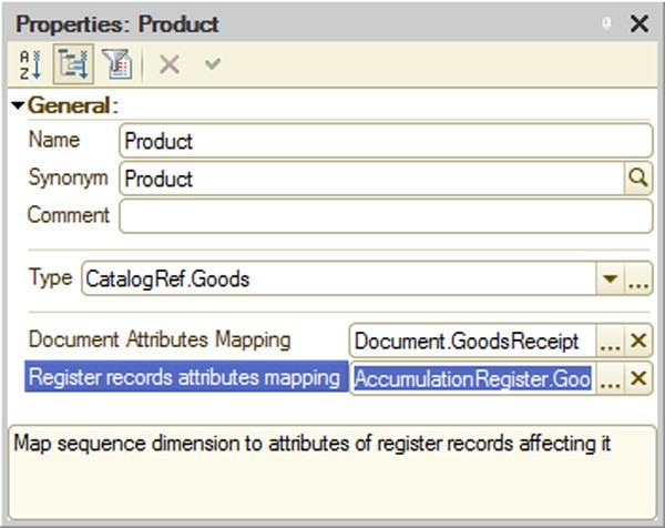
Fig. 124. Sequence Dimension Properties
Depending on the dimension type selected, document lists and dimension register lists only contain objects with the specified type of dimension.
Implementation of dimensions makes document reposting faster which is especially important for large volumes of documentation, since only documents containing the specified data will be reposted.
5.9.4.3. Work with Document Sequences
The 1C:Enterprise mode automatically maintains a sequence boundary for each document sequence in the configuration. Document position acts as the sequence boundary. During sequential posting of documents in a sequence, the sequence boundary is placed on each newly posted document. However, if you post a document that belongs to this sequence, but follows another posted document belonging to the same sequence and located after the current sequence boundary, the boundary does not change, as this would violate the sequence of posted documents. A document posting algorithm may be used to analyze such situations.
When documents are posted post factum, posting is cancelled, documents are deleted or register records that influence this sequence are deleted or written, the sequence boundary is moved to the time of the modified document. Before the boundary is moved backwards, the system checks if there are other boundaries to be moved backwards. This check does not require exclusive boundary lock.
Therefore, the sequence boundary will move forward with sequential posting of documents in this sequence and will move back if register records for this sequence are modified post factum.
There is a special feature to restore the document posting sequence in the document reposting mode (All functions – Standard – Document Posting). When this feature is used, the system automatically reposts all documents belonging to this sequence from the sequence boundary up to a specified location.
In the example with goods accounting, posted invoices will move the sequence boundary forward. If any modification of records in the register used for cost accounting of goods is written before the sequence boundary, it will move the boundary back to the time of this document. After that, posted documents positioned after the sequence boundary no longer move it forward if there are any posted documents of this sequence between the sequence boundary and the currently posted document. Restoring the sequence reposts all invoices. Please note that receipts, although influencing the sequence boundary, are not reposted, since their posting algorithm does not use balances and they are not included in the list of documents belonging to this sequence. After restoring the sequence, documents that are posted after the sequence boundary will move the boundary forward.
The Restore sequences mode makes it possible to automatically repost all documents related to the sequence from the current position of the sequence boundary to a specified moment. In this case you need to select a position that will limit the document reposting at the top of the dialog.
5.9.5. Entering Documents Based on Existing Objects
You can enter new documents in the 1C:Enterprise system based on existing objects. Users can enter documents or catalog items and enter their respective attributes by copying information from other infobase objects, such as documents or objects of other types.
The Generation tab lists the objects that can be used as a basis for the selected document type (the Can be generated based on field) and the objects that can be based on this document type (the Can be used as a basis for generating field).
To enable the generation procedure, you must implement the Filling event handler in the document module. For a description of the filling procedure see page 1-266.
The code of the handler may be adjusted by a system configuration specialist. The code of the handler should provide for certain information transfer operations depending on the type of source document, as well as other required operations.
Create Based On Wizard (see page 2-985) can be used to facilitate creation of this handler.
5.10. DOCUMENT JOURNALS
In 1C:Enterprise, document journals are objects that enable users to work with documents of various types. Users can enter, view and delete documents in journal forms.
Users can search for any document in a journal by column contents, search for a document by its number and filter documents by specific parameters.
You can create any number of journals in the Designer.
When a journal is created, you can create any number of screen forms for it. Screen forms contain table boxes that display the document type, number, date and time, as well as additional columns for other document attributes that are shown in each journal.
If no journal form is created, a default journal form will be created automatically in the 1C:Enterprise mode.
5.10.1. Journal Creation
The Document journals branch of the configuration tree is used for working with journals.
In 1C:Enterprise, journal creation and document placement processes are very closely related. Document representation in a journal is synchronized with journal data for documents the journal contains.
When both a journal and documents are created, a new document or journal will automatically be added to the list of journals and documents. To display document data in the journal it is necessary to specify the relationship, either in the journal or in the document. You can specify that a document belongs to a journal using both the journal and the document, since this operation is synchronized.
5.10.2. Journal Editing
This section describes journal-specific properties that supplement common properties of configuration objects (see page 1-250) and editing methods for Journal configuration objects that differ from the editing methods common for all configuration objects.
Journal properties (preparing additional column lists, column definition, journal forms, print form templates, etc.) are configured in the editing window (see page 1-59).
Use the Data tab to prepare a list of documents in a journal and a list of journal columns.
Each subordinate object at the Graphs branch contains a common attribute of all documents included into the journal (see below).
5.10.3. Document Journal Columns
When a new document journal is created in the configuration, you can create any number of journal forms for it. Journal forms can be created using the configuration object form wizard (see page 1-59). The wizard places a table box with a set of columns for different document attributes into the form. When you create a journal form, the form wizard creates the following columns: picture (the document status), type, date and document number. If you want to add more information to the journal, prepare a list of additional columns and place them in the forms.
The Data tab of the editing window contains a list of documents with data displayed in the journal. To create an additional column in the bottom list, add a Graph subordinate object and specify the attributes of documents with data displayed in this column.
To select the document attributes to be displayed in the journal column, click the selection button in the References property of the column's properties palette. The document attribute selection window will open.

Fig. 125. Attribute Selection for a Column
IMPORTANT!
You cannot select more than one attribute of the same document.
If an attribute of a document is not selected, the column of the document journal will contain no information for all documents of this type. Your selection should be based on common sense. It is not reasonable to include entirely different documents in the same column (e.g., a contractor description and a document's amount).
You can add any number of columns to the journal in addition to the obligatory document columns (Date, Number, Document type) and columns specified in the subordinate group of Graph journal objects.
If all the documents with a string type number in the journal have a fixed number length, then the Number column of the journal will also be of a fixed length. When at least one document with a string type number in the journal has a variable number length, then a Number journal column of variable length will be created.
A new column is first added to the column list of the selected Document journal object and is then inserted into a form using the Form – Insert Attributes menu item.
Availability of additional columns in the journal enables a user to get the most important information about a document without opening it.
For any form elements displaying a journal column, the following attribute properties included in the column are applied automatically:
Password mode – if this mode is set for any attribute included in the column.
Format – in case of match for all attributes included in the column on all languages specified in the configuration.
Tooltip – if tooltips match for all attributes, one tooltip is shown; if tooltips do not match, they are shown separated by a comma.
Highlight negative – if this property is set for all the attributes included in the column.
Multiline mode – if this property is set for all the attributes included in the column.
5.11. ENUMERATIONS
An enumeration is a service data type that is mainly used with other data types rather than independently. An enumeration is a list of possible attribute values.
Enumerations are used to enter document or catalog attributes and constant values when it is necessary to enter only predefined information.
As an example, let us take the customer status concept. In the simplest case, there may be retail and wholesale customers. Customer status usually influences the level of discounts.
This list of statuses (Retail and Wholesale) is actually a simple enumeration. When billing, the user has to specify the customer's status by selecting it from the list. The selected customer status influences the sales price.
If the customer status is entered as an enumeration during task configuration, a 1C:Enterprise configuration specialist may specify price calculation options depending on the status.
First of all, when you use it, the enumeration cannot be expanded since the list of its values was set during the enumeration setup.
All enumerations have only one level; no nesting is available.
The main feature of an enumeration is that its values are known and available in the Designer. The configuration itself uses specific enumeration values.
With enumerations, you can limit the number of possible options, e.g. when you enter a document attribute. Since enumeration value lists are created in the configuration, you can validate the selected value and specify the actions that should follow.
Use the Enumerations branch of the configuration tree to work with enumerations.
Editing an enumeration actually involves creating a list of values. To edit an enumeration object, use the Enumeration object editing window. The Include in the command interface property is disabled when a new enumeration is created.
Enter values for an enumeration at the Data tab.

Fig. 126. Adding an Enumeration Value
The properties palette contains a name and a synonym.
The list of enumeration values in the 1C:Enterprise mode is used as follows: each enumeration value is represented by a synonym or by a name if the synonym is not set.
In the above example (see fig. 127), the value of the ProductTypes enumeration will be displayed as Product (the specified synonym).
The Forms tab is used to create list and choice forms. You can create different selection forms (depending on the context). In list forms, enumeration lists can be printed. The Include in the command interface property is automatically enabled when a default list form is created.
You can create print templates at the Templates tab.
5.12. REPORTS AND DATA PROCESSORS
Any accounting system is functional only when it has the ability to process the accumulated information and to produce summary data that are easy to view and analyze. For this purpose, accounting systems usually have a report generation feature. The Designer makes it possible to prepare a set of different reports sufficient to meet system users' requirements for accurate and detailed output information.
Configuration objects located at the Reports branch of the configuration tree are used to generate reports in the 1C:Enterprise system. Each object of this type can contain an algorithm for generating paper or electronic reports written in the 1C:Enterprise script or a data composition schema used in 1C:Enterprise as a basis to auto-run reports (see page 1-536). A report may contain one or several forms which may be used to enter parameters that influence the algorithm, if necessary. A report may have print form descriptions (templates) that are created in the template wizard and used to display algorithm results on screen or print them out.
Use the editing window to edit properties of Report and Data processor objects and create subordinate objects (see page 1-59).
Configuration objects located at the Data processors branch of the configuration tree are used to handle information in 1C:Enterprise. For example, you can use them to delete obsolete data from the system, import information from other systems and for many other purposes. The name of the configuration object (Data processor) describes the actions that are performed with information, since they modify the information stored in the system.
A data processor may contain one or several forms which may be used to enter parameters that influence the algorithm, if necessary. Algorithm results are displayed or printed out using the template wizard for print form descriptions (templates).
The main difference between a report and a data processor is the ability to use the data composition schema (for details see page 1-531). All other features of data processors are identical to those of reports.
You can use the same report forms, report settings or variants for multiple (or all) application reports. You need to use common forms for this. In general, the following usage options are available:
A single report form set is used for all application reports. In this case you need to create the required forms and specify them in configuration properties (see page 1-167). Then you do not need to design forms in reports, since common forms will be used.
You can select report sets and design special report forms for every report set. In this case common report forms are created that are specified for every report of a corresponding group. Thus you can create a special form set, for example, for accounting reports and analysis reports.
NOTE
If several reports have the same default form specified as their main form, only one report can be opened in the thick client (in a regular mode).
5.12.1. External Reports and Data Processors
In 1C:Enterprise an external report is stored outside the configuration, in a separate external report file. It has the same purpose as the Report configuration objects.
In 1C:Enterprise an external data processor is stored outside the configuration, in a separate external data processor file. It has the same purpose as configuration objects of Report or Data processor type.
The main purpose of any external report (data processor) is implementing, delivering and updating specific features outside the configuration.
External reports and data processors are stored in .erf and .epf files, accordingly. You can develop and debug them as you work with 1C:Enterprise. In this case development and debugging is performed much faster: the external data processor (report) is edited and saved in the Designer mode without saving the entire configuration and is launched in the 1C:Enterprise mode. An external data processor (report) is launched using File – Open like any other data processor (report) in the configuration.
NOTE
External reports and data processors opened using File – Open are executed in safe mode (see page 1-182) if the user has no administrative access rights.
Any Report or Data processor configuration object may be copied to an external data processor (report) file or vice versa – a configuration object may be replaced by an external data processor (report).
You can create Help Content for an external data processor (report), just as for any other configuration object.
TIP
To ensure configuration integrity, it is recommended that external data processors (reports) be used mainly for debugging purposes. After debugging the algorithm of data processor (report) creation, it is necessary to include the external data processor to the configuration.
5.12.1.1. Creation of an External Data Processor (Report)
To create an external data processor (report), use File – New and select External data processor or External report in the dialog (see fig. 127).
This opens a form editor where you can develop an external data processor (report). For an external report, the editing window also contains controls that can be used to create, configure and edit the data composition system.
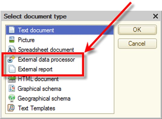
Fig. 127. Document Type Selection
Since an external data processor (report) is not a part of the current configuration (although it is closely linked to it), the procedure for saving it is different from the procedure for saving configuration changes (see page 1-48). To save an external data processor (report), use File – Save, File – Save As or File – Save Copy. In the standard saving dialog box, select the External data processor (*.epf) (External report (*.erf)) file type and enter the name for the external data processor (report).
5.12.1.2. Use of External Data Processors (Reports)
To use an external data processor (report) in 1C:Enterprise, you have to open it the same way as in the Designer. However, please keep in mind that an external data processor (report) in 1C:Enterprise can be opened only for execution and users cannot edit it. When the system attempts to open an external data processor (report), it checks access rights and sets the safe mode (if the user has no administrative privileges).
The external data processor (report) module is compiled when the external data processor (report) is opened. Therefore, after editing an external data processor (report) in the Designer and saving it, this data processor has to be reopened in the 1C:Enterprise mode.
Besides, you can work with external data processors (reports) at the 1C:Enterprise Server. In this case, all restrictions applied to using interactive objects (forms, etc.) are still valid.
If you want to use an external data processor (report) programmatically, you need to connect it to the server first, using the Connect() method (which is only available at the 1C:Enterprise Server).
//  Insert a data processor into a temporary storage at the client
StorageURL  = "";
Result  = PutFile(StorageURL,
"ExtDataProcessor.epf",
,
False);

...

//  Connect the data processor to the server from the previously created
//  temporary storage.
DataProcessorName  = ExternalDataProcessors.Connect(TempStorageURL);
The name of the external data processor is stored in the DataProcessorName variable. This name is later used to call the connected external data processor, e.g., to open the data processor form:
//  Open the form of the connected external data processor
OpenForm("ExternalDataProcessor."+  DataProcessorName +".Form");
A data processor (report) to be used programmatically can be saved at the following locations:
file stored in the configuration (e.g., a template)
infobase data
temporary storage (see page 2-841)
Names of external data processors (reports) must be unique within a single session. If you attempt to connect an external data processor (report) (programmatically or interactively) and its name is a duplicate of the name of a data processor (report) already connected to the current session, the system disconnects the previous data processor and connect the new one.
NOTE
If you use external data processors (reports) at the thick client, please note that in the managed mode you can only open managed forms, while in the ordinary mode ordinary forms are only available.
When using external data processors (reports), please keep the following in mind:
If you connect a new data processor (report) with the name identical to the name of a previously connected data processor (report), open forms of the older data processor (report) will not work (generate an error).
When an external data processor (report) is connected and this data processor (report) being connected is identical to the one already connected, and their safety mode property is the same, no actual re-connection occurs, no error is thrown. Alternatively, an external data processor (report) connected earlier is disconnected, and a new external data processor (report) is connected.
When method Create() is executed, the SafetyMode method parameter is ignored if the external data processor (report) was connected earlier with method Connect(). If no connection was set earlier, the SafetyMode parameter from method Create() will be used to connect an external data processor (report).
When you get a form for an external data processor (report), an open form is retrieved, regardless of whether it is opened for the currently or previously connected data processor (with the same name).
If you open a data processor (report) using File – Open, its form is opened with the help of the OpenForm() method (with Uniqueness set to True); it ensures a new data processor form can be opened in case of modifications.
5.12.1.3. Editing an External Data Processor (Report)
You can edit external data processors in the Designer.
Select File – Open to open an existing external data processor (report). Select the
External data processor (*.epf) (External report (*.erf)) file type in the standard dialog box and specify the file name.
When an external data processor (report) is opened, the Designer automatically opens the object editing window. Unlike other configuration objects, you can edit an external data processor (report) without restarting 1C:Enterprise. After saving the data processor (report) in the Designer, you simply need to reload it in the 1C:Enterprise mode.
5.12.1.4. Help Content
An external data processor (report) can have a custom description. To edit a description, click the Open link for the Help content property in the properties palette of the external data processor.
To view an external data processor (report) description in the 1C:Enterprise mode, press the F1 key.
5.12.1.5. External Data Processors (Reports) and Configuration Objects
Existing Report and Data processor configuration objects can be converted into external reports and data processors and vice versa. External reports and data processors can also be added to the configuration structure as new configuration objects of the Report or Data processor type.
Copying a Data Processor (Report) to External Data Processor (Report)
An existing Report or Data processor configuration object may be copied to an external data processor or report. To do this, select the object name in the Configuration window and select Save as External Data processor, report from the context menu. Select the External data processor (*.epf) (External report (*.erf)) file type in the standard Save File dialog box and specify the file name for the external data processor (report).
A new external data processor (report) will be created. It will be a copy of the selected configuration object. The configuration object itself will not change.
This operation is useful for further debugging of a report or data processor. When debugging is completed, you can re-insert the external data processor or report into the configuration.
Replacement of a Data Processor (Report) with an External Data Processor (Report)
An external report or data processor may replace an existing Report or Data processor configuration object.
To replace a configuration object with an external data processor (report), select its description in the Configuration window and click Replace to External Data processor, report in the context menu. Select the External data processor (*.epf) (External report (*.erf)) file type in the standard Open File dialog box and specify the file name for the external data processor (report).
Addition of an External Data Processor (Report) to Configuration Structure
An existing external data processor (report) may be added to the configuration structure as a new Report or Data processor configuration object. To do this, select any Report or Data processor configuration object in the configuration structure and click Insert External Data processor, report in the context menu. Select the External data processor (*.epf) (External report (*.erf)) file type in the standard Open File dialog box and specify the file name for the external data processor (report) to be inserted into the configuration structure.
A new data processor (report) will be created in the configuration tree.
5.12.1.6. Comparison and Merge of External Data Processors (Reports)
External data processors (reports) may be compared and merged with configuration data processors (reports) or with other external data processors (reports).
To do this, select the required object in the Configuration window and click
Compare and Merge with External Data processor, report in the context menu. Select the required external data processor (report) in the standard file selection dialog box.
The Compare and Merge… window will open. Actions available in this window are identical to those in the Merge Configurations window (see page 2-1074), see fig. 128.
To compare or merge an external data processor (report) with another external data processor (report), open the source external data processor (report) in the editing window, click the Actions button and select Compare and Merge with External Data processor from the drop-down list. Select the external data processor (report) you need in the standard file selection dialog. For a description of further actions see page 2-1074.
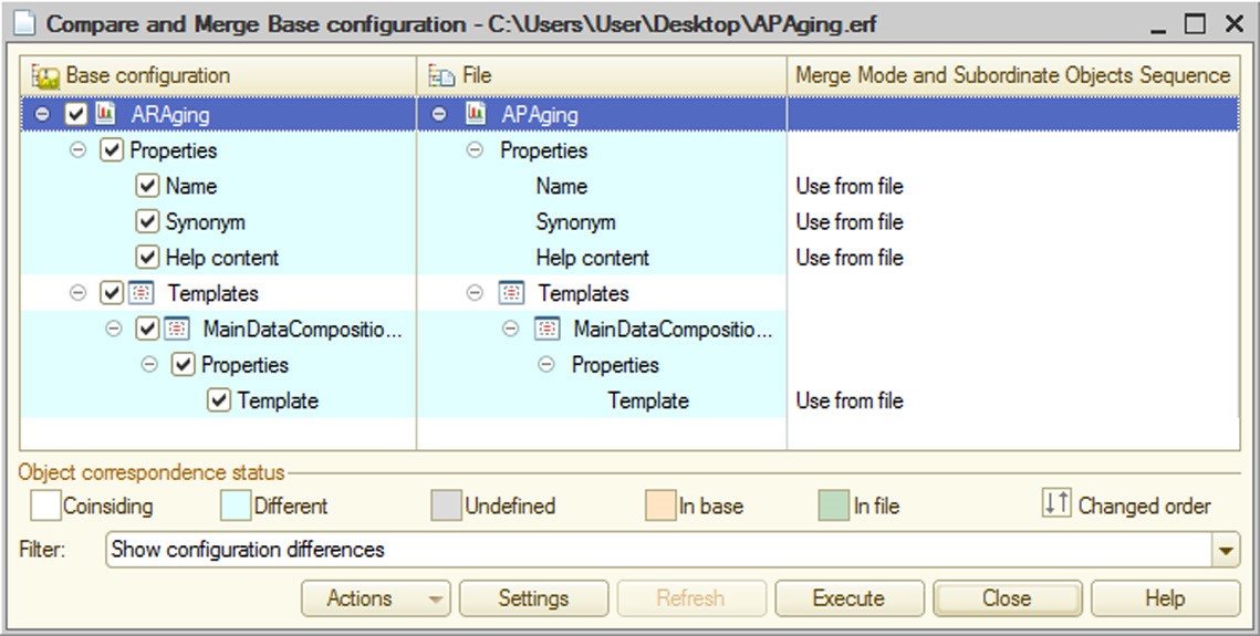
Fig. 128. Merging Data Processors
5.13. CHARTS OF CHARACTERISTIC TYPES
1C:Enterprise uses Charts of characteristic types to describe the characteristics of analytical accounting objects.
Objects of this type may be used to describe the characteristics of goods or contractors. They are used for analytical accounting for extra dimensions (not for subaccounts) in the chart of accounts. Chart of characteristic types do not describe a specific product or account; they only reference the description. Thus, management accounting often has to describe not only mandatory features of goods like their description, price, article and vendor, but also other features, such as color, best before date, size, weight, flavor etc. Of course, different types of goods will have different features (e.g., for footwear you need to specify the size, width, color, material and other features, but these features are not needed for computer equipment). In this case it is sufficient to create the required description schemas at the object level of the configuration and select the required description type (characteristic type) for a specific item.
You can use the 1C:Enterprise Designer to create any number of charts of characteristic types as required for analytical accounting purposes.
Working with Chart of characteristic types objects is similar to working with Catalog objects. Objects may also form hierarchical structure. They have the same subordinate objects: they can be created and edited as an item, as a list or in both ways, etc.
Configuration developers may create a set of predefined items for Chart of characteristic types objects. These items cannot be deleted in the 1C:Enterprise mode. However, configuring Chart of characteristic types objects has some differences.
A Chart of characteristic types object may have a Characteristic value type property which makes it possible to define a list of valid data types used for characteristic types. Value types are selected on the Main tab of the object editing window.
A composite data type is usually used. This ensures you can specify the required value when entering a specific characteristic. For example, the ProductCharacteristicTypes object of the chart of characteristic types is used to specify extra dimension types for charts of accounts. This object has a composite type of a characteristics value (see fig. 130).

Fig. 129. 'Product Characteristic Types' Chart of Characteristic Types
Thus, when Chart of characteristic types objects are used to describe the structure of a chart of accounts, extra dimension types will be selected from predefined list of characteristic types. When a specific account is created, specify which extra dimension types are linked with this account.
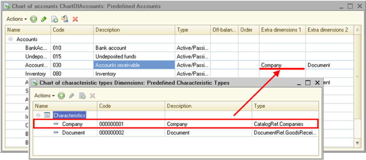
Fig. 130. Using Extra Dimension Types
As the figure shows, account 30 Accounts receivable has two extra dimension types – Company and Document – which are selected from a set of predefined characteristic types specified in this chart of characteristic types.
To maintain accounts for a characteristic that has no description (catalog) in the configuration, use the Additional characteristic values property of the chart of characteristic types. For example, you need to maintain accounts by cost centers, but the configuration does not contain an appropriate catalog. In this case you can create a custom CostCenter characteristic type and specify that items of an additional catalog will be used as values for this characteristic type. Since this catalog is subordinate to the chart of characteristic types, only catalog values subordinate to the characteristic type may be selected. It means values of different types will not be mixed.
IMPORTANT!
When primitive types (Number, String or Date) are selected in the Characteristic value type property, specify the size or contents of the type in the value type editing window so that this description covers all possible values. If fractional parts are not specified for numeric types, you will not be able to enter fractional numbers. Changes in the description of numeric data after a user has entered values may result in data loss.
To create predefined items in the Chart of characteristic types object editing window, click Predefined at the Other tab. The window for predefined items will open.
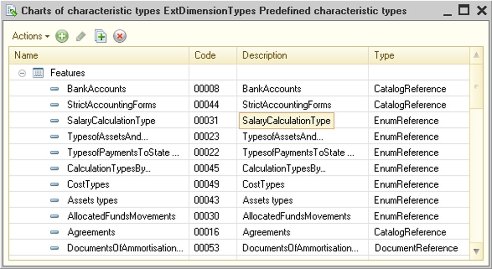
Fig. 131. Predefined Items in Charts of Characteristic Types
Maintenance actions for predefined characteristics are available in the Actions menu.
Predefined and custom items have different icon types in the 1C:Enterprise mode.
In the 1C:Enterprise mode, you can change the value type for custom characteristic items.
How to Create and Use a Chart of Characteristic Types: Example
Please review a sample structure of data used to store characteristics (irrelevant table fields are omitted).
Nomenclature Catalog
Description
Vega 700 Telephone
Vega 300 Telephone Omega Copier
NomenclatureCharacteristicTypes Chart
of Characteristic Types
Description
Weight
Lifetime
Paper size
Main vendor
NomenclatureCharacteristics Information Register
|
Description (dimension) |
CharacteristicType (dimension) |
CharacteristicValue (resource) |
|
Ref: Vega 700 Telephone |
Ref: Weight |
70 |
|
Ref: Vega 700 Telephone |
Ref: Lifetime |
120 |
|
Ref: Vega 300 Telephone |
Ref: Weight |
50 |
|
Ref: Vega 300 Telephone |
Ref: Lifetime |
80 |
|
Ref: Omega Copier |
Ref: Weight |
1300 |
|
Ref: Omega Copier |
Ref: Paper size |
A4 |
|
Ref: Omega Copier |
Ref: Main vendor |
Ref: Priborpostavka |
Contractors Catalog
Description
Ref: Priborpostavka
Add metadata objects (catalogs, a chart of characteristic types and an information register) with the specified structure to the configuration.
When you attempt to implement this example in the configuration, you will face an important question. You do not know what type needs to be selected for the CharacteristicValue resource of the NomenclatureCharacteristics register.
In practice, characteristics differ both in their use and value types. This is where features specific to charts of characteristic types acquire importance. Unlike catalogs, charts of characteristic types can contain descriptions of characteristic value types. Metadata for charts of characteristic types include the Type property that describes characteristic value types. This property's type is TypeDescription; it must include all value types available for various characteristics. For example, in this case you can specify the following types for the NomenclatureCharacteristicTypes chart of characteristic types:
String, length: 20;
Number, format: 15.2;
CatalogRef.Contractors.
This set of types must ensure all characteristic values in the example can be stored. After you select values for the Type property (characteristic value type) in the chart of characteristic types, the list of available types will display Characte- ristic.NomenclatureCharacteristicTypes.
Now, when selecting the CharacteristicValue resource type you can specify the type (Characteristic.NomenclatureCharacteristicTypes) defined by the chart of characteristic types. Please note that the type you should select is Characteristic.NomenclatureCharacteristicTypes, not ChartOfChartOfCharacteristicTypesRef.NomenclatureCharacteristicTypes. By selecting the Characteristic.NomenclatureCharacteristicTypes type, you define the resource type indirectly, i.e. you do not specify specific types; instead, you specify that the set of types is defined by the types selected in the property of the chart of characteristic types.
Therefore, creating the chart of characteristic types you determine that the database can store a list of product characteristic types and define the range of valid characteristic values.
In addition to describing value types for all characteristic types, charts of characteristic types can also be used to store value types for each characteristic type in the database since metadata are used to specify types for all possible characteristic types, while individual characteristic types can have values of specific types. For example, weight must be a numeric value.
For this purpose, charts of characteristic types support a ValueType field. This field's type is TypeDescription; it is used to describe valid types for specific characteristic types. Therefore, the chart of characteristic types in this example will have the following data structure:
NomenclatureCharacteristicTypes Chart of Characteristic Types
|
Description |
ValueType |
|
Weight |
Number |
|
Lifetime |
Number |
|
Paper size |
String |
|
Main vendor |
CatalogRef.Contractors |
All objects required to store characteristics have been described. Please note, however, that Nomenclature and CharacteristicType dimensions are unrelated in the system. Therefore, when you enter characteristic values the system ignores the selected characteristic type; instead, it prompts you to fill in the field using all types described in the chart of characteristic types.
Structure description for the information register has no information about logical links between the fields that store characteristic types and values. In real-life solutions this logical link can be quite complex. A characteristic type can be stored in other objects and defined by a complex algorithm that depends on the subject area. This is why a relationship between characteristic types and values are configured by the configuration developer.
In this case you need to configure a relationship between characteristic type and value in order to enter information register records.
To do this, set the Link by type property for the CharacteristicValue resource to CharacteristicType.
Now, if a user changes the characteristic type and the existing value does not match characteristic types for the selected value type, the value is cleared.
If you want to try this example out, you should make another minor change in the configuration. Set the Master property for the Nomenclature dimension of the NomenclatureCharacteristicTypes register. It removes characteristic data when goods are deleted and displays the Open Information Register command in the catalog navigation panel.
Now you can check if the characteristic storing procedure is fully implemented. Open the Nomenclature catalog item, select the Nomenclature characteristics hyperlink in the navigation panel and start entering characteristics for a specific item. As you enter the characteristics, you can create new characteristic types and select their value type.
The implemented solution has a major drawback. You have enabled entry of primitive-type characteristics and reference types defined in the configuration. This example uses a catalog of contractors to enter the main vendor. It is obvious, however, that some properties need to have their values selected from lists. On the other hand, lists of values for various properties are different. Accordingly, you cannot select values for these properties from catalogs existing in the configuration. In this example paper size is entered as a string. It would be more convenient to select a value for this property from a list of available sizes; however, you cannot create catalogs for each characteristic type in the configuration, since catalogs are created at the configuration development stage, while new characteristic types are entered as you use the application.
Charts of characteristic types can help you deal with this issue. You can use a subordinate catalog to store values of characteristics that cannot be selected from catalogs, enumerations and other content existing in the configuration.
Create a CharacteristicValues catalog and specify it is subordinate to the NomenclatureCharacteristicTypes chart of characteristic types. Next, select this catalog as a value for the CharacteristicExtValues property of the chart of characteristic types. Additionally you need to add a CatalogRef: CharacteristicValues type to the Type property of the chart of characteristic types.
Now the chart of characteristic types can use the CharacteristicValues catalog for characteristic value lists. Change ValueType for the Paper size characteristic type by selecting CatalogRef: CharacteristicValues. When you fill in the characteristic value, you will be prompted to select it from the catalog list limited by the owning Paper size characteristic type.
The structure of data in the resulting example will look like the following:
Nomenclature Catalog
Description
Vega 700 Telephone
Vega 300 Telephone
Omega Copy Duplicator
NomenclatureCharacteristicTypes Chart of Characteristic Types
|
Description |
ValueType |
|
Weight |
Number |
|
Lifetime |
Number |
|
Paper size |
CatalogRef: CharacteristicValues |
|
Main vendor |
CatalogRef: Contractors |
|
Casing color |
CatalogRef: CharacteristicValues |
NomenclatureCharacteristics Information Register
|
Description (dimension) |
CharacteristicType (dimension) |
CharacteristicValue (resource) |
|
Ref: Vega 700 Telephone set |
Ref: Weight |
70 |
|
Ref: Vega 700 Telephone set |
Ref: Lifetime |
120 |
|
Ref: Vega 300 Telephone set |
Ref: Weight |
50 |
|
Ref: Vega 300 Telephone set |
Ref: Lifetime |
80 |
|
Ref: Omega Copy Duplicator |
Ref: Weight |
1300 |
|
Ref: Omega Copy Duplicator |
Ref: Paper size |
Ref: A4 |
|
Ref: Omega Copy Duplicator |
Ref: Main vendor |
Ref: Electronica |
Contractors Catalog
Description
Priborpostavka
CharacteristicValues Catalog
|
Owner |
Code |
Description |
|
Ref: Paper size |
1 |
A3 |
|
Ref: Paper size |
2 |
A4 |
|
Ref: Casing color |
3 |
White |
|
Ref: Casing color |
4 |
Silver |
You can use charts of characteristic types to enter characteristic types as you work with the infobase. However, you can also create predefined characteristic types in the configuration. You are recommended to create these types as values corresponding to the operation logic of the configuration, rather than as default characteristic types. An example could be a New Year discount percentage. If you enter this characteristic for a product, the price calculation algorithm can use it to define a selling price in the period preceding the New Year.
5.14. REGISTERS
1C:Enterprise registers are mainly used to store and process information about the company's business or organizational activities.
Document and Catalog type infobase objects are used to store information about actual objects of a subject area, such as employees, goods, material and currency. Each database object corresponds to an actual object of a subject area.
Registers usually store information on changes in the status of objects or other information that does not directly reflect subject-domain objects. For example, registers can hold information on currency exchange rates or information on the receipt and dispensing of merchandise.
A database object is independent of its attributes and has its own value. For example, an employee may change their last name, passport number or any other attribute. However, the employee will still be the same individual.
After you delete an object, you cannot create it again. Even if you make all of an object's attributes the same as those of the deleted object, it will be a different object. The system stores an internal object ID – a reference. A reference is unique within the entire infobase. No two objects may have the same reference in the entire lifetime of the infobase. References of the deleted objects are not assigned to new objects. Database object references may be stored in database fields.
The information in registers is stored in records. Use of a register record depends only on the data that are stored in this record. For example, a currency exchange rate record does not represent anything material. It does not correspond to any physical object. The only important factor is that it contains currency, a date and the exchange rate set for this date. This record may be deleted and replaced with the same record, but this will not affect the logic of the system. Accordingly, register records do not have references and references to register records may not be stored in database fields.
This section describes information and accumulation registers. For information about accounting registers see page 1-660; for information about calculation registers see page 1-668.
5.14.1. Information Registers
Here you will learn, what an information register is and how information registers should be used.
5.14.1.1. Data Register Overview
The main purpose of an information register is to store existing information for the application task, whose makeup extends to a certain combination of values and when necessary, extends over time. For example, if we want to store information about competitors’ prices for the goods that we sell, this information could be expanded by adding goods or competitors. If we also want to track price movements and if we enter this information periodically, the stored information can be expanded over time, as well.
1C:Enterprise uses a special mechanism – information registers – for storing these data and working with them.
An information register is a multi-dimensional data array needed to implement a function that provides the required information for a specific set of arguments. Function arguments are called dimensions and function results are called resources. In the example given above, the two-dimensional register CompetitorsPrices will have Competitor and Product as its dimensions and Price as its resource. You can have more than one resource. For example, you can store the wholesale and retail prices.
In addition to dimensions and resources, you can create a set of attributes for an information register. Attributes can be used to add any information to register records. Attributes do not influence values of register resources and may be used to analyze register records.
Information registers whose data extend over time are called "periodic". For periodic information registers, the system also supports standard operations such as getting the latest or earliest value (for example, getting the last price entered for a particular product and a particular competitor) and also getting a slice of the latest or historical values. For example, all the latest prices for various goods and competitors can be retrieved.
To expand the information over time, use the Period field in the register. It is not entered as a dimension, but is automatically added by the system when a periodical register is created.
It is not necessary to create dimensions for information registers. In this case a register is actually a set of periodical data. Such registers may be used to store the last names of the officers responsible for signing documents. Documents are created and signed by officers with the right of signature at a certain point in time. For information on how to use constant values for these purposes see page 1-279. One drawback of this method is that when the value of a constant changes, a new name will be shown in archive documents. In such cases, it is necessary to use a periodical information register instead of a constant. This periodical information register stores information about changes and documents use values from the information register depending on the date.
Currency exchange rate is the most typical example of a one-dimensional periodical value. When some calculations are performed (e.g., when a price in dollars is determined by recalculating a price in euro according to the exchange rate), it is important to know this value at the time of the calculation.
It is especially important to know the currency exchange rate when performing certain calculations post factum. In this case it is necessary to recall the exchange rate for past dates.
To make it possible to obtain such information, it is necessary to create a table that contains three columns: currency name, date and currency exchange rate. The rows of this table contain the exchange rates for several currencies on a specific date.
|
Date |
Currency |
Rate |
|
31.10.2008 |
USD |
26.5430 |
|
31.10.2008 |
EUR |
35.0447 |
|
01.11.2008 |
USD |
27.0981 |
|
01.11.2008 |
EUR |
34.4092 |
|
02.11.2008 |
USD |
27.0793 |
|
02.11.2008 |
EUR |
34.4828 |
When you open a table like this, please keep in mind that the Rate column contains specific exchange rates for a certain date and it is assumed the rate does not change for all the following dates until the next rate is available. Therefore, to obtain the exchange rate for an intermediate date, you should take the rate for the closest previous date with a recorded exchange rate.
It is also necessary to remember that different values in the Currency column mean that a parallel history of exchange rates is maintained for several currencies.
In other words, the table shown above can be represented in a different way:
|
Date |
USD Rate |
EUR Rate |
|
31.10.2008 |
26.5430 |
35.0447 |
|
01.11.2008 |
27.0981 |
34.4092 |
|
02.11.2008 |
27.0793 |
34.4828 |
Such a table may contain any number of columns, depending on the number of currencies for which exchange rates need to be stored.
If a register is not periodical, no Period field is created for it. In the example above, the CompetitorPrices register may be non-periodical if you do not want to store the price change history (you only need the current prices). In this case the register function can be used to tell us what a specific competitor's price is for a specific good currently, but it will not be able to tell what the price was at the beginning of the year.
These principles imply that the system can only have one record with a specific set and period of dimensions. In fact, there really can be only one price for each product of each competitor. If, for any reason, we can obtain multiple prices and want to store this information in the database, we need to create another dimension to store a value that makes these prices different. For example, you can create an InformationSource dimension. In this case we will be able to enter competitors’ prices from different sources.
Uniqueness of the records in a dimension set makes information registers fundamentally different from accumulation registers where multiple records can be entered with the same value and period.
If receiving data as of the very first moment or the most recent (current) moment is the most frequent use of the register, then it makes sense, with regard to such registers, to allow the system to support totals for the slice of the last data (Allow totals: section of last property) or the slice of the first data (Allow totals: section of first property). An example of such use is a register with the sales prices of goods. The item price can change, but queries for the current price are the most common queries to this register.
Information register totals will be used if all of the following prerequisites are met:
Totals use in the configuration is allowed for the register.
Totals use in 1C:Enterprise mode is allowed for the register.
Data as of the very first date (the slice of the first data) or the last (current) date (the slice of the last data) is received without specifying the period value.
Conditions for the SliceFirst and SliceLast virtual tables are set only for values of dimensions and separators that are in the Independent and Shared mode.
Only dimensions and separators in the Independent and Shared mode are used in data access restrictions.
If none of the above is met, the standard query is used to get the information from the register.
5.14.1.2. Information Register Records
Lines of the information register containing information about resource values for specific dimensions and specific periods, are called records. A record key can be used to identify information register entries. Records may be entered into the information register in two ways:
Manually
Using documents
For information on selecting the record entry method see page 1-320.
These two options only influence the way the information is entered and have no impact on the main principle of the register functioning.
A document that enters a record into the information register is called a recorder.
Registers that are recorded independently may be freely edited manually or using the 1C:Enterprise script tools. If a dimension of such a register is assigned as the master dimension and its value is a reference to a database object, this record will make sense only while this object exists. For example, if you specify Competitor dimension as the master dimension, it is considered that this record makes sense as information about this competitor. Correspondingly, when a competitor is deleted, all related records will be deleted automatically.
If a register is maintained by a recorder, this means that the records in this register will be strictly subordinate to the recorder documents. Usually it means that records are created when documents are posted. When a document is deleted, the records will be deleted automatically. Unlike master dimensions, there may be only one recorder.
You should remember that an information register record key created with the help of the EmptyKey() method is not equal to the information register record key, the dimension values of which are equal to default values for its own types.
5.14.1.3. Information Register Editing
The Information registers branch of the configuration tree is used to work with information registers.
Editing a register includes specifying its properties and developing its structure: sets of dimensions, resources and attributes, screen forms for viewing and editing records and (if necessary) print forms (see page 1-59).
Here you will find information about properties specific to information registers. They supplement common properties of all configuration objects.
Use the Information register editing window to edit registers. Register properties are arranged in tabs (see fig. 132).
Periodicity. This property defines how often resource values are saved in the register.

Fig. 132. Information Register Editor
This property directly influences the possibility of obtaining register resource values using the 1C:Enterprise script methods. For a non-periodical register, you can obtain only the last entered value of a register resource – information from previous periods is not available in such a register. For periodic registers, a value with a periodicity smaller than the specified register periodicity cannot be obtained.
Periodicity does not depend on the register editing type.
Write mode. This property determines how records are entered: independently (for example, manually) or subordinate to the recorder (for example, using documents).
If a register is periodical and the independent write mode is selected, the Include period in the main filter property becomes available. If this option is checked, in addition to the main dimensions and attributes of the register, the user can also filter records by the Period field.
The Data tab is used to generate the data structure of a register. Use it to create dimensions, resources and attributes.
The Recorders tab is used to manage the list of recorders. This tab is available only if the Write mode property is set to Subordinate to recorder (see fig. 133).
The top list is used to manage the recorder list (check or uncheck boxes) and the bottom list contains the selected recorder objects.
Similarly to managing the recorder list in information registers, you can manage recorder lists in registers of other types.

Fig. 133. Setting Recorder for an Information Register
Resources in an information register can have a wide variety of data types, while other registers can only contain numeric resources.
For a description of how to create forms and templates see page 1-47.
5.14.1.4. Development of Information Register Structure
To develop an information register structure, you need to create sets of dimensions, resources and attributes.
To manage a register's list of dimensions, resources and attributes and edit their properties, use the Dimensions, Resources and Attributes folder controls in the Register editing window. The setup procedure for the items of these folders is identical. For information about how to use these controls see page 1-59. Properties of Information Register Dimension (Resource, Attribute)
Properties of dimensions, resources and attributes are edited using the properties palette. They are mainly the same as common properties of all configuration objects. Unique properties of dimensions, resources and attributes are described below.
Master. This property is meaningful for dimensions that contain a reference to configuration objects. If this property is turned on, the information register record is meaningful only as long as this object exists. If the object is deleted, all related records will be deleted from the register.
No Empty Values. If this option is checked, register records cannot have empty dimension values.
Index. This dimension property may be edited for non-master dimensions. For dimensions, resources and attributes with the Index property turned on, a separate index is created, thus increasing register performance. Index is always created for master dimensions.
When a register is viewed in the 1C:Enterprise mode, you can sort register records by indexed dimensions, resources and attributes. The required number of forms for register viewing and editing has to be created at the configuration development stage.
Ordering Information Register Dimension List
The arrangement of an information register's dimensions is very important.
If you need quick access to some dimensions, place them at the beginning of the list.
The sequence of information register dimensions influences the possibility of using 1C:Enterprise script methods that employ positional access to dimensions.
You should also remember that changing the order of dimension requires restructuring of the infobase.
5.14.2. Accumulation Registers
Accumulation registers are used in 1C:Enterprise to store information about availability and movements of certain values (material, cash, etc.). All data on commercial transactions that are entered using documents or generated using calculations must be accumulated in registers. In this case they can be retrieved, analyzed and displayed to a user in report forms.
Here you will learn about accumulation registers and the basic principles of using them.
5.14.2.1. Accumulation Register Overview
An accumulation register is a configuration object designed to store register records and total data.
A typical problem you may face when creating a summary information "storage" is the structure decisions: what points to choose for accumulating the summary data to ensure a simple retrieval of the required information. The 1C:Enterprise system uses simple but flexible means to generate accumulation registers. You only need to specify what points and data need to be stored in the register, and the system itself will ensure recording and retrieval of data using simple language resources.
The 1C:Enterprise script methods allow to retrieve accumulation register balance for a specified point in time. You can filter data by dimension values or obtain balances by other dimensions.
Consider the following example. Say you are creating a sales and warehouse accounting program and you need to store information about the quantity and price of each product in each warehouse. You want to get information such as the remaining inventory of a specific product at a specific warehouse, the remaining inventory of a specific product at all warehouse, the cost of all goods at warehouse, etc.
In 1C:Enterprise, such an accumulation register is a rectangular system of coordinates. One of its axis contains warehouses, the other – goods. The intersections between goods and warehouses contain the values of a product's quantity and cost.
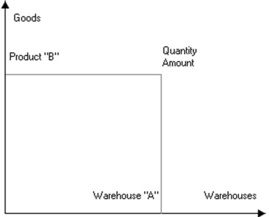
Fig. 134. Accumulation Registers
It is hard to explain the physical meaning of an accumulation register, since it does not have any material counterpart.
IMPORTANT!
Therefore, let us specify that an accumulation register is an n-dimensional system of coordinates for storing joint data. The axes of such coordinate systems are called register dimensions and the stored data are called register resources.
5.14.2.2. Records of Accumulation Registers
The state of accumulation registers usually changes when a document is posted. The document posting procedure is located in the document module. It contains an algorithm of generating data on register changes to be made when the document is posted. This information is called register records. The totals calculation mechanism uses register records to make direct changes in accumulation registers. Therefore, register records contain only increments (positive or negative) of register resource values, not the total values.
A system configuration specialist can allow end users to track register records. The Designer can be used to create screen and print forms for viewing and analyzing register records.
You can create any number of accumulation registers at the configuration development stage. However, you should remember that if there are too many accumulation registers, this might reduce system performance during document posting.
In addition to dimensions and resources, you can also create a set of attributes for an accumulation register. Attributes may be used to add any information to register records. Attributes do not influence values of register resources and may be used to analyze register records.
5.14.2.3. Totals of Accumulation Registers
As pointed out above, register changes are implemented by register records. Register records influence the register's totals. Totals are summarized register information obtained by summing up the values of register records.
The totals of an accumulation register may be represented as a table with a number of columns equal to the number of dimensions and resources in the accumulation register. The number of rows in the table depends on the number of different dimensions and resources:
|
Product |
Warehouse |
Count |
Total |
|
Table |
Retail |
10 |
5 000 |
|
Table |
Wholesale |
5 |
2 500 |
|
Cabinet |
Temporary |
7 |
10 500 |
|
Cabinet |
Wholesale |
2 |
3 000 |
|
Cabinet |
Retail |
10 |
15 000 |
You can see in the table that the Product dimension has the Table and Cabinet values, while the Warehouse dimension has the Temporary, Wholesale and Retail values. The Count and Total columns for the accumulation register's resources contain the quantity and total value for each product at the warehouse.
Unlike register records, you cannot view totals of accumulation registers directly. To obtain totals information, you can create any number of reports in the configuration. These report will query the totals and display them as product reports, warehouse cards, lists, etc.
5.14.2.4. Balance Registers and Turnover Registers
In the 1C:Enterprise system, you can use two types of accumulation registers: balance registers and turnover registers.
Balance registers can use the 1C:Enterprise script methods to get accumulation register balances for a specified point in time. You can filter data by dimension values or obtain balances by other dimensions.
Turnover registers are used to store information that cannot have any balance, e.g., sales volume for different customers.
As an example, review how settlements with buyers of goods manufactured or sold by the company (or consumers of the company's services) are tracked. This kind of accounting is usually mandatory for every enterprise.
To be able to obtain current information about how much the enterprise and one of its customers owe each other, it is necessary to use a Settlements register which will store the amount of debt for each customer. When a business transaction occurs, the register is updated according to the current state of settlements. The Settlements register is a balance register.
However, it is impossible to obtain information about volumes of purchases for a specific customer in a certain period of time from the Settlements register, since it does not store this information. Therefore, additional effort is required to get this information: for example, you can include a Contractor attribute in the register structure, then select register records for each contractor, and calculate the total amount of purchases. However, if you need this information in real time (e.g., when a customer is eligible for a discount upon reaching a certain volume of sales), this method is not applicable.
In this case you can use a turnover register. This register (let us call it Purchase Volume) will store information about sales volume for each customer (turnover with the customer).
Now, for business transactions, it would be necessary to change both the Settlements register and the Purchase Volume register. After each purchase, information about the amount of the purchase will be recorded to this register. As a result, the Purchase Volume register will constantly accumulate information about the total volume of purchases made by the client.
All of this makes the advantages of registers quite clear.
First of all, registers are used to store information that needs to be accessed quickly. A 1C:Enterprise configuration specialist must determine whether information is needed quickly and whether it is necessary to use a register, based on the requirements of system users.
Registers also make it possible to obtain the most accurate information about current funds. As the processes of saving documents and recording changes in registers are separate (a document may be saved without posting), the data in documents and in registers may differ. However, registers (unlike documents) are a storage of totals information, i.e. changes recorded in registers confirm completion of a business transaction.
5.14.2.5. Main Properties of Accumulation Registers
The Accumulation registers branch of the configuration tree is used to work with accumulation registers.
Use the editing window to edit properties of Accumulation register objects and create subordinate objects (see page 1-59).
When you edit an accumulation register, you specify its type and develop its structure:
Create sets of register dimensions, resources and attributes;
Create screen and print forms to view register records, if necessary.
NOTE
Such values as UUID, BinaryData, and any unlimited length string cannot be the accumulation register dimension type.
This section describes unique properties of accumulation registers that supplement common properties of all objects.
Register Type specifies if a register can be used: To store balances (select Balance from the list), To store turnovers (select Turnovers).
See page 1-325 for a description of the differences between the balance register and the turnover register.
Default List Form. A register may contain several forms for tracking its records. If there are multiple forms for entering and selection, you can specify the default form in the Default List Form property.
Enable totals split. If this check box is set to True (default value), totals splitter mechanism is used to ensure a greater concurrency of writing to the register. If the system writes records in multiple concurrent sessions, it does not update the same totals records; it writes each change in the totals as a separate record. To obtain totals, these values are summed. This way, totals are kept up-to-date (this is useful for quick generation of reports, for example) and register records can be made concurrently. This mode requires more resources (for instance, the amount of data in totals tables is bigger in this case). This is why both the configuration and the 1C:Enterprise script contains properties that manage this mode.
Records multiply only when transactions are performed concurrently. Their quantity for each combination of dimensions depends on the maximum number of concurrent transactions. When recalculating totals, separate accumulated records are collapsed.
The totals splitting mode can be modified by the user in the 1C:Enterprise mode. By default this property is enabled.
Use in totals. If this check box is set to False, the dimension is excluded from the stored register totals.
Several forms can be created to view the register records. If there are several forms for data input and selection, you can specify the form to be used by default in the Default List Form property.
5.14.2.6. Aggregates of Accumulation Turnover Registers
You can use aggregates to boost system performance when using accumulation turnover registers. Aggregates can be represented as special storages that can be used with queries in 1C:Enterprise. Major Concepts
Terms used to describe aggregate operation are defined below in this section.
Aggregate is a physical database table that stores summary totals for all register resources by the selected dimensions with the specified periodicity in a specific period. If a register uses aggregates, it can have up to 30 dimensions.
Aggregates are defined by the following parameters:
Aggregate size: aggregate table size. Estimate.
Effect: expected reduction in average time of query execution with aggregates. For example, if the aggregate effect is 90%, it means the average time of query execution with aggregates is 90% less than the average time of executing the same query with totals. Estimate.
Aggregate period is a range of dates used to insert data in the aggregate.
Aggregate periodicity is periodicity used to store data in the aggregate.
Aggregate list is a set of aggregates created at the configuration stage. The list can be either manually generated or loaded from a file resulting from the calculation of optimal aggregates.
Use statistics is information about the type of queries (dimensions, period and periodicity) to the recorder. These data allow you to rebuild aggregates and obtain an optimal aggregate list.
Optimal aggregate list is a list of aggregates with an optimal size-effect correlation for the register in its current state (register records and use statistics).
Aggregates/totals mode: If you select the aggregates mode, queries are executed using aggregate data; if you set the totals mode, queries use totals data.
Use aggregates: You can disable use of aggregates to perform no operations with aggregates when register records change. It makes sense to disable aggregates while you mass-load data into the registers; however, enabling aggregates later could require a lot of resources to update the aggregates (if the modified data fall within the aggregate period).
General Flowchart for Working with Aggregates
Review the following general flowchart for working with aggregates (see fig. 135).
NOTE
This flowchart demonstrates how to work with a single register. If you want to work with multiple register, you need to perform every step for each individual register.
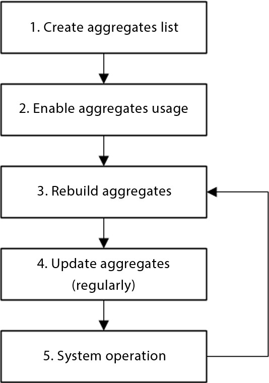
Fig. 135. General Flowchart for Working with Aggregates (client/server variant)
Let us examine the working procedure in greater detail:
1. Create a list of required aggregates in Designer. This is an optional step. Creating aggregates in Designer mode can be used if the constant use of an aggregate in any infobase needs to be supported.
There are several ways to create aggregates in Designer:
○ Calculate (i.e., in totals mode) and load optimal aggregates (DetermineOptimalAggregates()). If aggregates have not been previously used, a list of optimal aggregates will be received on the basis of the register record table. If aggregates have been previously used, a list of optimal aggregates will be built on the basis of a table of records and the usage statistics. ○ Create an own list of aggregates based on register queries analysis.
2. After the database configuration is updated, enable aggregate mode for the register (SetAggregatesMode()method).
3. You then need to rebuild aggregates on a regular basis (RebuildAggregatesUsing()method). During this operation, the system adds the required aggregates and deletes ones that are not used. This operation is performed if the current list of aggregates is not optimal. Only the aggregates created during the rebuilding operation are deleted. The aggregates created in Designer are not deleted automatically, and if the aggregates are created in Designer, the following actions will be taken during the rebuilding operation:
○ An aggregate will be enabled if the aggregate’s use case is set to Always.
Performance evaluation of the aggregate does not impact its usage.
○ If the aggregate’s use mode is set to Auto, the aggregate will be enabled based on performance evaluation. The use of this aggregate is evaluated together with the aggregates automatically created by the system. If an automatically created aggregate performs better than the aggregate created in Designer with Auto use mode, an automatically created aggregate will be used instead.
4. Aggregate updating must be completed afterwards (UpdateAggregates() method). When aggregates are updated, data from the selected register records table is moved to the corresponding aggregate tables. The records created in the records table after the previous aggregate update are moved.
5. Next, the usage statistics of the aggregates created should be accumulated. To do this, perform standard tasks that use data from the register for which the aggregate mode has been enabled within a certain period of time (e.g., within 1 month). Regular aggregate updates must be performed while working. When the period ends, rebuild the aggregates (step 3) and perform steps 3–5 on a regular basis.
The described schema details an approach to working with the register’s aggregates in a client/server mode.
Working with aggregates differs a little when it comes to file-based usage of the system:
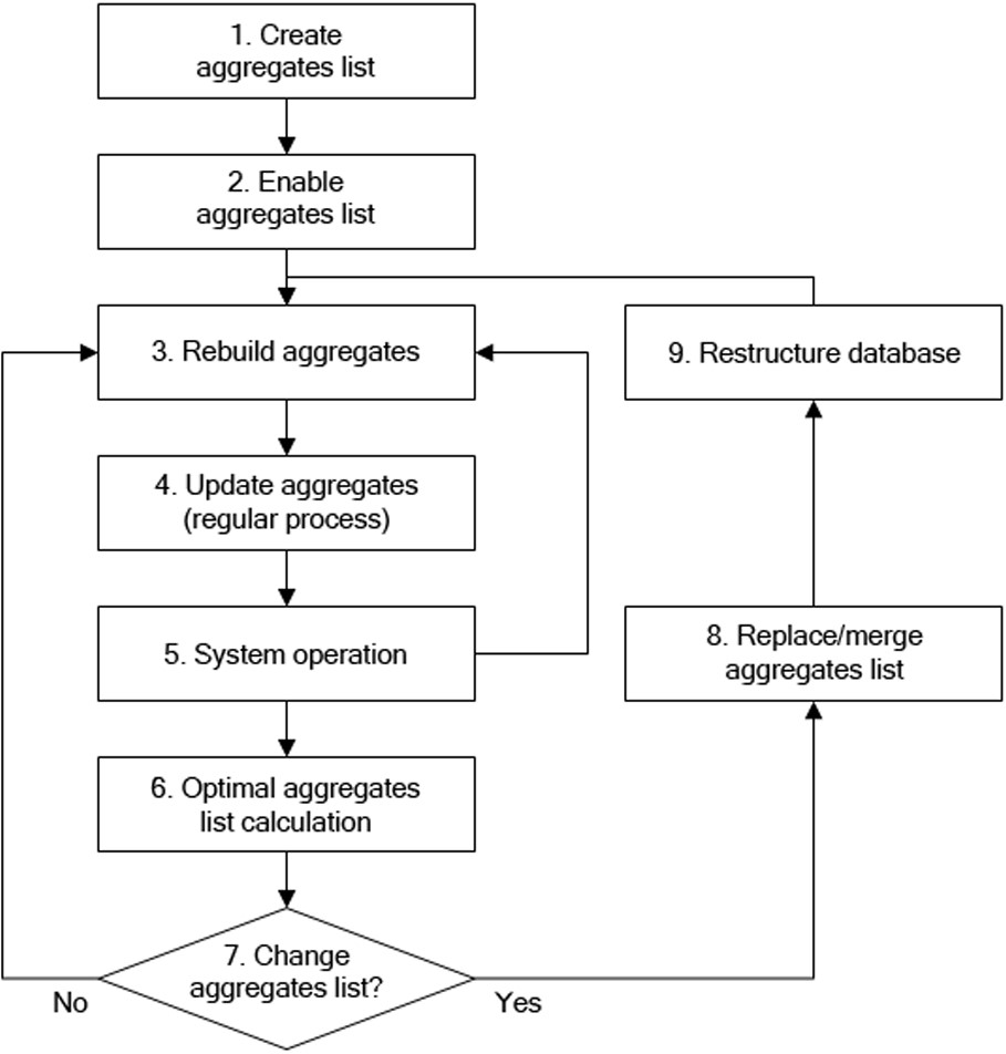
Fig. 136. Working with aggregates (file-based variant): an overview
The major differences between this approach and a general approach to working with aggregates (see fig. 137) is as follows (only the differences are described):
At step 1 a list of aggregates must be created in Designer.
Step 6. Recalculation of optimal aggregates (DetermineOptimalAggregates() method) should be performed regularly (e.g., once a month). During this period (1 month), standard tasks that use data from the register for which the aggregate mode has been enabled should be performed. Regular aggregate updates are needed while working.
Step 7. When a new list of optimal aggregates is received, the user needs to define whether or not a list of aggregates needs to be changed in the configuration metadata. If no changes are required, proceed to step 3.
Step 8. If a list of aggregates needs to be updated, load the required (or all) aggregates (from a list of optimal ones). Update the database configuration (the infobase will be restructured) and then proceed from step 3.
For guidelines on each of these steps, see the next section.
Recommendations on How to Use Aggregates
Generation of Aggregate List
You can generate a list of aggregates using one of the available methods.
If you want to enable aggregates for a register that exists in the configuration, but has never used aggregates, you can do the following:
If the register has no or few records (up to 2 or 3 thousand records), analyze queries that use this register to obtain a list of frequently used dimensions, filters, query periods and data retrieval periodicity. Based on the information you obtain, create a list of aggregates while minimizing the number of aggregates.
If the register uses a big number of records (more than three thousand), you can calculate optimal aggregates based on the register data using the DetermineOptimalAggregates() method and then load the resulting list of aggregates.
If the register you use already has the aggregates mode and use enabled (i.e. the initial list of aggregate has been generated), you can also retrieve a list of optimal aggregates and load it in the Designer. This method is different from method 2, since in this case the calculation of optimal aggregates uses the system statistics. Therefore, the resulting list of aggregates is more efficient compared to the list obtained for a register with the disabled aggregates mode and use.
NOTE
Optimal aggregates method is convenient, only if the table of register records contains at least three to five thousand records. If the number of records is below this figure, the obtained list of aggregates might prove inefficient.
Rebuilding
You should rebuild aggregates at least as often as you calculate the list of optimal aggregates. This operation does not modify the list of aggregates; instead, it attempts to use the existing aggregates only.
You should also keep in mind that the rebuilding operation is only efficient if you have a considerable amount of statistical data.
Although it is hard to recommend when you need to rebuild aggregates in the most general case, major factors can be pointed out:
when it is probable the nature of register data has changed;
when it is possible the nature of queries has changed (which modifies the accumulated statistics).
When you perform the operation, you are required to specify two parameters:
Maximum relative size – limits the size of the generated aggregate list (percentage of the record table size). If it is set to zero, there is no limit on the aggregate list size.
Minimum effect – percentage of improvement in the process of rebuilding the older list. If the new list improves the effect by the specified value, the method rebuilds the list. If the parameter has no value or is set to zero, there is no minimum effect requirement.
The current list of aggregates is also rebuilt if its size exceeds the value in the Maximum relative size, % parameter or the resulting list is at least as efficient as the double value of the Minimum rebuild effect, % parameter. Otherwise the list of aggregates is not rebuilt.
NOTE
The rebuilding operation takes a lot of time and resources. You are not recommended to run this operation when other users actively use the infobase.
Aggregate Update Operation
You are recommended to run this operation more often than the aggregate rebuilding operation.
You can update aggregates in two ways:
Run a complete update of all aggregates marked as used. This might take a long time.
Use the so-called "partial" filling. In this case a single run updates 10 aggregates for a period of one month.
When you perform this operation, you should indicate the Maximum relative size. It limits the size of the generated aggregate list (as percentage of the record table size). If set to zero, there is no limit on the aggregate list size.
NOTE
You are recommended to run this operation when the load on the infobase is minimal.
TIP
You are recommended to use the totals splitting mode when using aggregates, especially if aggregates are updated by a scheduled job and at the same time documents are posted for a register that updates the aggregates.
Use of aggregates
To define an aggregate to be used for a query, use the algorithm described below.
A query defines the register dimensions to be used, selects a list of aggregates that contain all dimensions used and match the query by frequency and period the best. Next, an aggregate with the minimum size is selected from the list. This is the aggregate that will be used.
A query may use an aggregate with a lower frequency than the frequency set in the query. In this case, the required data will be obtained by adding data from shorter periods.
Sometimes a period specified in the query does not match the aggregates period. In this case, two aggregates can be used to execute a query. Let us take a look at an example. For instance, an infobase includes two aggregates that cover the entire query period:
With monthly periodicity; With daily periodicity.
The query is executed for the period from September 15 to November 15. In this case, two aggregates will be used:
An aggregate with a monthly periodicity will be used to obtain data from October 1 to October 31;
An aggregate with a daily periodicity will be used to obtain data from September 15 to September 30 and from November 1 to November 15;
Data from the different aggregates will be added together to obtain the final result.
A virtual turnover table of the register for which the aggregate mode is enabled always contains actual data.
Optimal Aggregate Calculation
You can run this operation as needed; it is not regular. Below is a list of conditions when you are recommended to calculate optimal aggregates:
when some time elapses after you generate the initial aggregate list;
if performance reduces significantly as you use the current aggregate list;
if data nature changes significantly;
if the set of queries to the register changes;
if it is probable that the current aggregate list is no longer optimal.
NOTE 1
This operation is optional for the client/server variant. Optimal aggregates are created automatically (if necessary) when aggregates are rebuilt.
NOTE 2
This operation takes the longest time and the biggest amount of resources. We strongly recommend running it only when other users do not work with the infobase.
Using scheduled jobs when working with aggregates
Rebuild and refresh aggregate operations can be executed with scheduled jobs. You should follow the recommendations below when creating a schedule for performing scheduled jobs:
For a scheduled job that performs rebuild and refresh operations, setting the Key property of a scheduled job is recommended (see page 2-827).
Setting a schedule for scheduled rebuild and refresh jobs is recommended to avoid simultaneous execution of rebuild and refresh operations.
If you follow these recommendations, you can prevent simultaneous execution of rebuild and refresh operations, which positively affects performance.
Aggregate Editing
You can only create and edit a list of aggregates for an accumulation turnover register (the Register Type property is set to Turnovers). If you want to call the aggregate wizard, use the Open aggregates command in the register context menu.
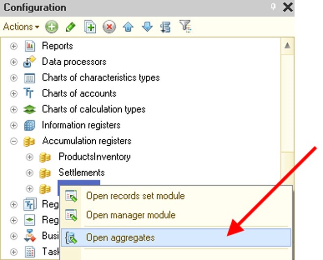
Fig. 137. Calling the Aggregate Wizard
It opens the aggregate wizard window where you can manage aggregates of an accumulation turnover register. You can manage aggregates manually or load a ready-to-use list of optimal aggregates (use a special button at the command bar).

Fig. 138. Aggregate Wizard
As you create aggregates, you can specify their use. If it's Auto (by default), the system independently determines whether an aggregate needs to be used during the aggregate rebuilding operation. If Always is selected, the system always uses this aggregate.
The Periodicity column defines the minimum time period for storing totals for the selected dimensions in the aggregate. You are allowed to have multiple aggregates with identical dimension sets and differing periodicity. Be sure not to overuse aggregates. A big number of aggregates can excessively expand the database without increasing query performance.
You can use the right-hand area of the window to indicate dimensions to be included in the edited aggregate. An aggregate can contain any number of dimensions (up to 30) or have no dimensions. In this case summary turnovers for the register are saved with the specified periodicity.
If the list of optimal aggregates is stored in an xml-file, you can load this list. To do this, use a special command of the aggregate wizard (see fig. 139) and select the ready-to-use list.

Fig. 139. Loading Optimal Aggregate List
The system compares the list from the file with the current aggregate list and highlights the aggregates recommended to be added (from the Optimal Aggregates list) and the aggregates recommended to be deleted (from the Aggregates list). You can choose not to implement the recommendations or implement them partially.
5.14.2.7. Development of Accumulation Register Structure
To develop a register structure, you need to create sets of dimensions, resources and attributes at the Data tab (see page 1-59).
Properties of Accumulation Register Dimension (Resource, Attribute)
Properties of dimensions, resources and attributes are edited using the properties palette. They are mainly the same as common properties of all configuration objects. Unique properties of dimensions, resources and attributes are described below.
Type. Unlike dimensions and attributes, Resource objects may store only Number data type.
No Empty Values. Check this option to disable writing register records with empty dimension values.
Index. This option may be specified only for dimensions. When you turn this property on, it speeds up operations with the register data, for example, when records by a specific dimension are selected. Such operations include queries with specified dimension value, temporary calculations and methods of bypassing AccumulationRegister object records in the 1C:Enterprise script using dimension-based filter.
Use in totals. If this property is not set, dimensions are excluded from the stored register totals (this property is only used for turnover register records). If a dimension of this type is used in a query or condition of a virtual table, the table does not use the stored totals; instead, it calculates data based on the record table only.
Ordering Accumulation Register Dimension List
The order of dimensions in the accumulation register affects the access to register totals. Place the dimensions that require fast access in the beginning of the dimensions list.